
Devices, systems, and methods for reshaping a heart valve annulus, including the use of magnetic tools

a heart valve and annulus technology, applied in the field of devices, systems and methods for reshaping the heart valve annulus, can solve the problems of leaflets that flail, valve malfunction, chordae tendineae (the chords) being stretched, etc., and achieve the effect of increasing the strength of the magnetic coupling

Inactive Publication Date: 2008-04-17
VENTURE LENDING & LEASING IV
View PDF10 Cites 156 Cited by
  • Summary
  • Abstract
  • Description
  • Claims
  • Application Information

AI Technical Summary

Benefits of technology

[0040] Another aspect of the invention provides a plurality of magnetic portions configured to provide both attractive and repulsive forces and this increase the strength of the magnetic coupling between the first and second catheters.

Problems solved by technology

Valve malfunction can result from the chordae tendineae (the chords) becoming stretched, and in some cases tearing.
When a chord tears, the result is a leaflet that flails.
Also, a normally structured valve may not function properly because of an enlargement of or shape change in the valve annulus.
This condition is referred to as a dilation of the annulus and generally results from heart muscle failure.
In addition, the valve may be defective at birth or because of an acquired disease.
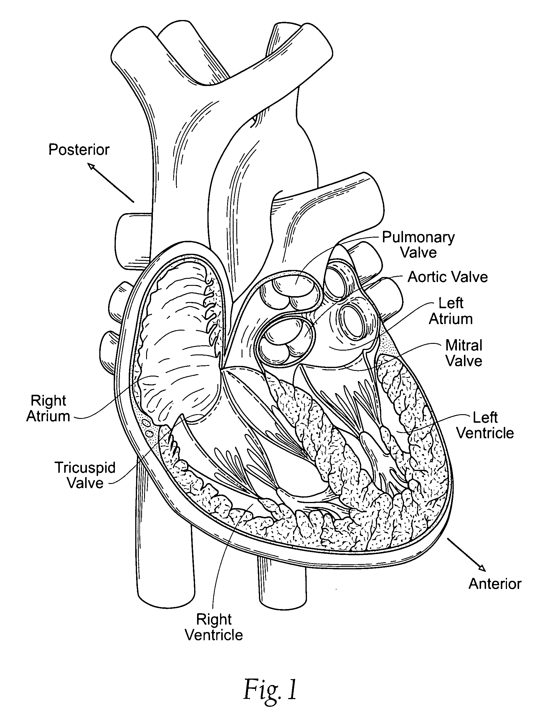
As a result, an undesired back flow of blood from the left ventricle into the left atrium can occur.
First, blood flowing back into the atrium may cause high atrial pressure and reduce the flow of blood into the left atrium from the lungs.
As blood backs up into the pulmonary system, fluid leaks into the lungs and causes pulmonary edema.
Second, the blood volume going to the atrium reduces volume of blood going forward into the aorta causing low cardiac output.
Excess blood in the atrium over-fills the ventricle during each cardiac cycle and causes volume overload in the left ventricle.
Organic mitral regurgitation results from a structurally abnormal valve component that causes a valve leaflet to leak during systole.
Functional mitral regurgitation is a significantly aggravating problem for the dilated heart, as is reflected in the increased mortality of these patients compared to otherwise comparable patients without functional mitral regurgitation.
This is because, in organic mitral regurgitation, the problem is not the annulus but in the central valve components.
After surgery, the repaired valve may progress to high rates of functional mitral regurgitation over time.
The problem with surgical therapy is the significant insult it imposes on these chronically ill patients with high morbidity and mortality rates associated with surgical repair.

Method used


Image

  • Devices, systems, and methods for reshaping a heart valve annulus, including the use of magnetic tools
  • Devices, systems, and methods for reshaping a heart valve annulus, including the use of magnetic tools
  • Devices, systems, and methods for reshaping a heart valve annulus, including the use of magnetic tools

Examples


Embodiment Construction

[0122] Although the disclosure hereof is detailed and exact to enable those skilled in the art to practice the invention, the physical embodiments herein disclosed merely exemplify the invention which may be embodied in other specific structures. While the preferred embodiment has been described, the details may be changed without departing from the invention, which is defined by the claims.

I. Trans-Septal Implants for Direct Shortening of the Minor Axis of a Heart Valve Annulus

[0123] A. Implant Structure

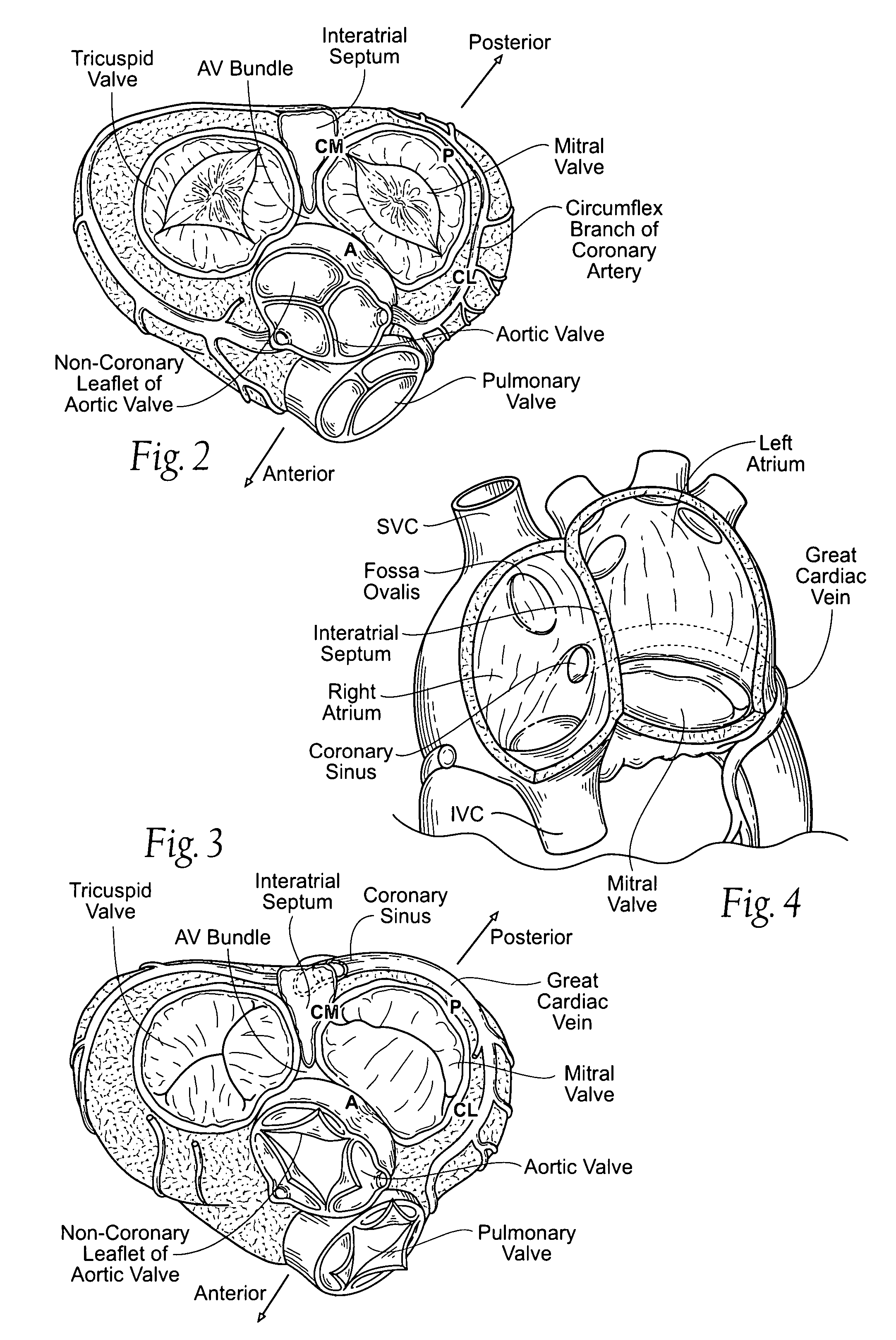
[0124]FIGS. 10A to 10C show embodiments of an implant 10 that is sized and configured to extend across the left atrium in generally an anterior-to-posterior direction, spanning the mitral valve annulus. The implant 10 comprises a spanning region or bridging element 12 having a posterior bridge stop region 14 and an anterior bridge stop region 16.

[0125] The posterior bridge stop region 14 is sized and configured to allow the bridging element 12 to be placed in a region of atrial...


PUM


Abstract

Implants or systems of implants and methods apply a selected force vector or a selected combination of force vectors within or across the left atrium, which allow mitral valve leaflets to better coapt. The implants or systems of implants and methods make possible rapid deployment, facile endovascular delivery, and full intra-atrial retrievability. The implants or systems of implants and methods also make use of strong fluoroscopic landmarks. The implants or systems of implants and methods make use of an adjustable implant and a fixed length implant. The implants or systems of implants and methods may also utilize a bridge stop to secure the implant, and the methods of implantation employ various tools.

Description

RELATED APPLICATIONS [0001] This application is a continuation-in-part of co-pending U.S. patent application Ser. No. 11 / 089,939, Filed Mar. 25, 2005, and entitled “Devices, Systems, and Methods for Reshaping a Heart Valve Annulus, Including the Use of Magnetic Tools,” which is a continuation-in-part of co-pending U.S. patent application Ser. No. 10 / 894,433, filed Jul. 19, 2004, and entitled “Devices, Systems, and Methods for Reshaping a Heart Valve Annulus,” which is a continuation-in-part of co-pending United Stated patent application Ser. No. 10 / 677,104, filed Oct. 1, 2003, and entitled “Devices, Systems, and Methods for Reshaping a Heart Valve Annulus,” which claims the benefit of U.S. patent application Ser. No. 09 / 666,617, filed Sep. 20, 2000 and entitled “Heart Valve Annulus Device and Methods of Using Same,” which is incorporated herein by reference. This application also claims the benefit of Patent Cooperation Treaty Application Serial No. PCT / US02 / 31376, filed Oct. 1, 200...

Claims


Application Information

Patent Timeline
Patent Type & Authority Applications(United States)
IPC IPC(8): A61F2/24
CPCA61B17/0057A61F2/2445A61B2017/00588A61B2017/00592A61B2017/00597A61B2017/00606A61B2017/00615A61B2017/00619A61B2017/00623A61B2017/00876A61B2017/0414A61B2017/0417A61B2017/0441A61B2017/0453A61B2017/0454A61B2017/0496A61F2/2451A61F2/2466A61F2/2487A61F2002/30079A61F2002/30668A61F2210/009A61F2250/0001A61B2017/00575A61B2017/1132A61B2017/1139A61B2017/1135A61B17/11A61B2017/0419A61B17/00234A61B2017/00243A61B2017/00783A61M25/09A61M2025/09175
Inventor MACHOLD, TIMOTHY R.CHANG, ROBERT T.RAHDERT, DAVID A.SCOTT, DAVIDTHOLFSEN, DAVID RAINNE
Owner VENTURE LENDING & LEASING IV
Learn More