Continuous Intermeshing Agitator Food Cooker

a technology of intermeshing agitator and food cooker, which is applied in the field of continuous steam cooker, can solve problems such as poor mixing

Inactive Publication Date: 2008-04-17
MARITEK
View PDF13 Cites 15 Cited by
  • Summary
  • Abstract
  • Description
  • Claims
  • Application Information

AI Technical Summary

Benefits of technology

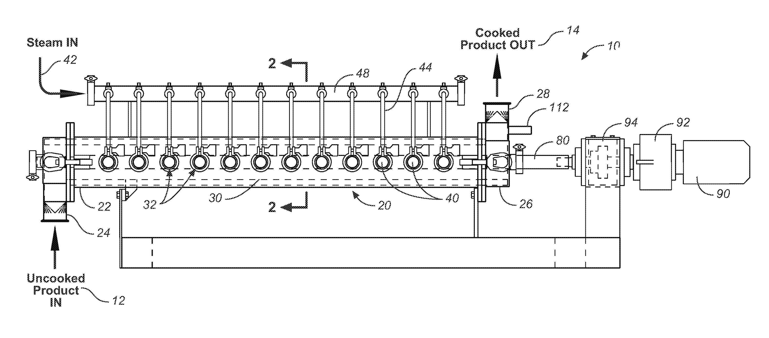
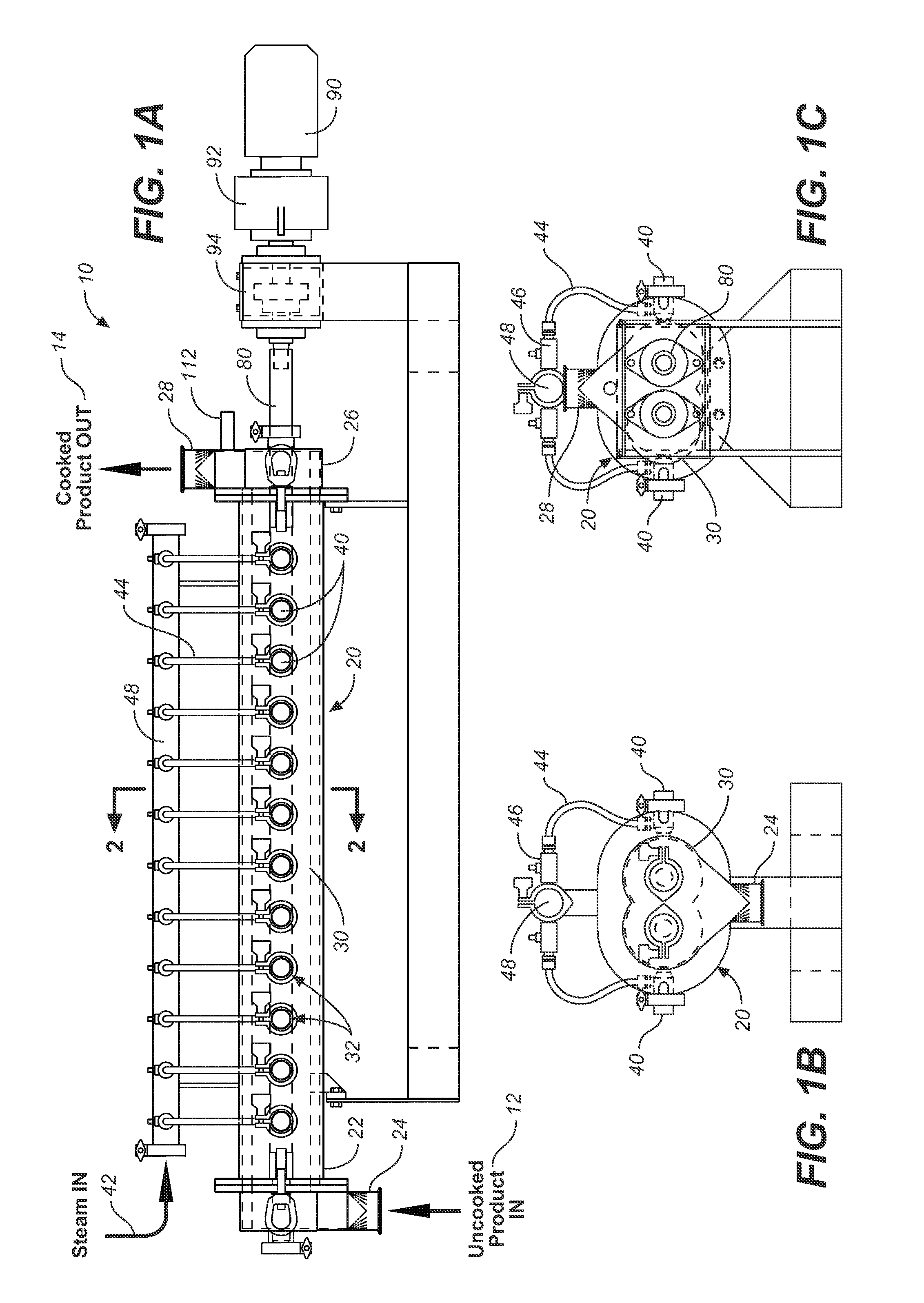
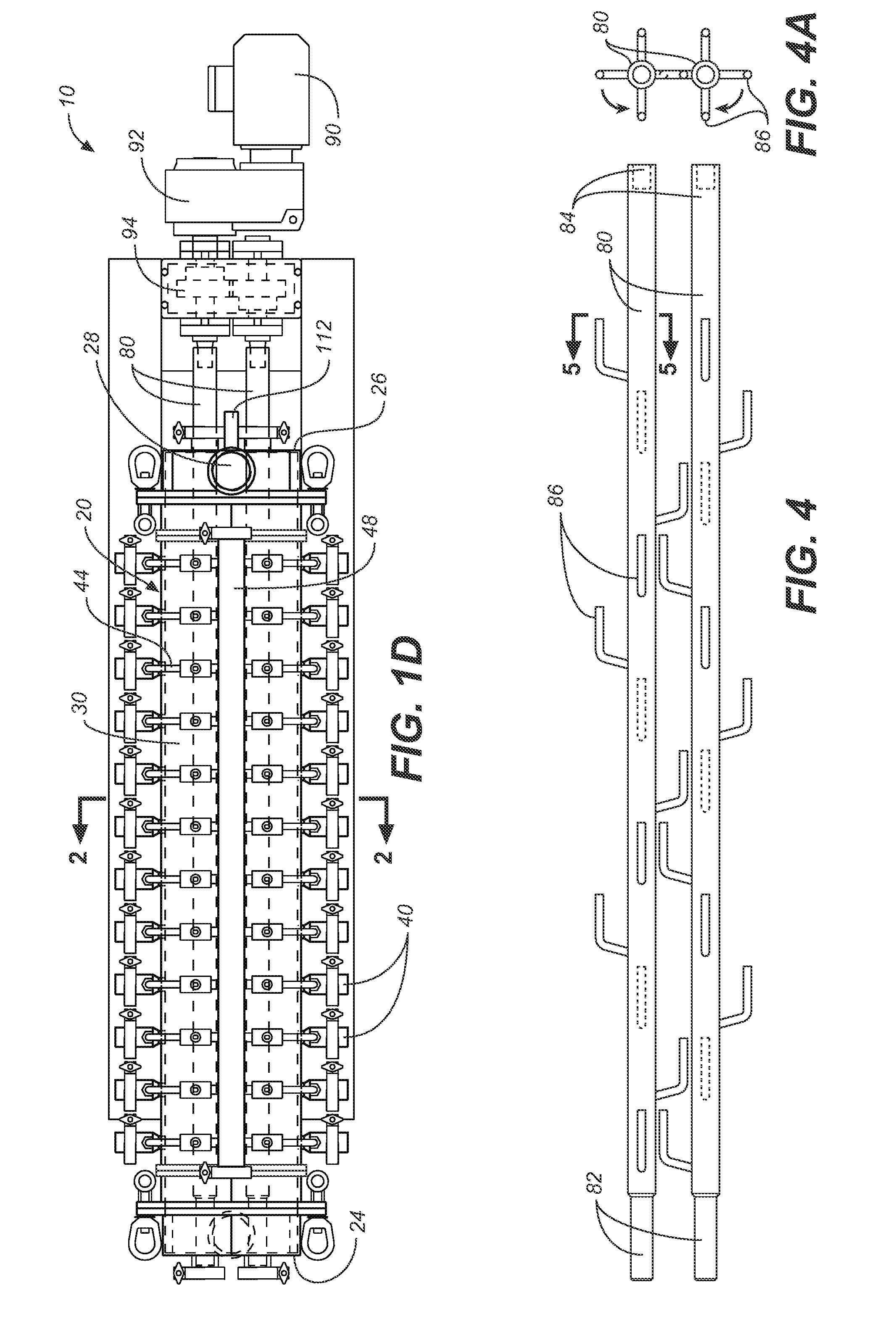
[0028]The present invention is a dual intermeshing agitator continuous direct steam cooker that receives a pump-able product from a positive displacement metering feed pump into the inlet end of the cooking chamber from the bottom and discharges the product out the discharge end at the top. The speed adjustable positive displacement metering pump determines the throughput rate of the product through the cooker. This throughput rate is completely independent of the RPM of the agitators, allowing the agitators to mix the product at the most optimal RPM necessary without changing the production throughput rate.

Problems solved by technology

The affect of gravity on the product assists in keeping the product from cylindering (i.e., rotating with the agitator with resulting poor mixing).

Method used


Image

  • Continuous Intermeshing Agitator Food Cooker
  • Continuous Intermeshing Agitator Food Cooker
  • Continuous Intermeshing Agitator Food Cooker

Examples


example 1

a Cheese Production

[0084]A typical target for pH of mozzarella cheese curd being fed into the mozzarella cooker would be 5.08 at a temperature of 80 degrees F. With a production rate of 5000 lbs per hour a typical inlet steam supply pressure would be 120 PSI, the injectors would be set to open in sequence starting with the first injector at the inlet of the cooker and to open as necessary to reach the set point temperature setting with a temperature setting of the outgoing, heated mozzarella cheese set at 140 degrees F. Ideally the agitator RPM would be set at 100 RPM. With the dual intermeshing agitator cooker one would expect these settings to produce excellent mozzarella cheese. If the pH of the cheese curd was 5.20 the set point temperature of the cooker would be raised to 145 degrees F. to compensate for the increased pH and minimize the loss of cheese moisture and milk solids. If the cheese came out of the cooker with evidence of small, unmelted cheese curd lumps the RPM speed...

example 2

Meat Production

[0085]In the case of the cooking of ground beef taco meat, the incoming raw meat temperature would be approximately 35 degrees F. At a production rate of 5000 lbs per hour the cooked meat temperature set point would be set at 155 degrees F. and the agitator RPMs set at 250. The steam injector set up recommended is to spread out the heat input the length of the cooking column with the sequence of the opening of the injectors spaced out, opening every third injector until the temperature set point is reached. If the particle size of the cooked ground beef coming out of the cooker is too small the agitator RPM should be reduced 25 RPM at a time until the particle size is correct. If there are uncooked lumps of meat coming out of the cooking chamber the temperature set point should be increased by a few degrees or the agitator RPM increased by 25 RPM. If both the particle size is too small and the meat has uncooked lumps, location of the open steam injectors need to be mo...


PUM


Abstract

A method and apparatus for continuous cooking of a pumpable food product including a process chamber 20 having an inlet end 22 and an inlet port 24 for introducing food product 12 into the chamber, an outlet end 26 and an outlet port 28 for the discharge of the cooked food product 14, and a central portion between the two ends with a plurality of steam inlets 32 arrayed along the walls of the central portion; inside the chamber at least two non-conveying agitator 80 with arms 86 depending for mixing and kneading food product; a drive means 90 for the agitators; a loading device 102 to feed a pump 100 that introduces food to the cooking chamber and provides the motivation to discharge the cooked food product through the outlet; and a controller 110 that monitors and controls the inlet pump, the steam inlet valves and the agitator speed and direction which all impact the quality characteristics of the cooked food product.

Description

CROSS REFERENCES TO RELATED APPLICATIONS[0001]The present application claims the benefit of U.S. Provisional Patent Application Ser. No. 60 / 851,654, filed Oct. 12, 2006 (Oct. 12, 2006).SEQUENCE LISTING[0002]Not applicable.STATEMENT REGARDING FEDERALLY SPONSORED RESEARCH OR DEVELOPMENT[0003]Not applicable.THE NAMES OR PARTIES TO A JOINT RESEARCH AGREEMENT[0004]Not applicable.INCORPORATION-BY-REFERENCE OF MATERIAL SUBMITTED ON A COMPACT DISC[0005]Not applicable.FIELD OF THE INVENTION[0006]The present invention relates generally to commercial cooking apparatus, and more particularly to a continuous steam cooker having intermeshing, non-conveying agitators, specially adapted for cooking pasta filata cheese.BACKGROUND DISCUSSION OF RELATED ART[0007]There are a variety of different continuous direct steam cooking systems in use today. Most of the continuous direct steam cooking systems are designed with an auger or screw to convey the product through the cooker. This type of cooker does n...

Claims


Application Information

Patent Timeline
Patent Type & Authority Applications(United States)
IPC IPC(8): A23L1/01A47J27/04A47J36/00A23L5/10
CPCA23C19/0684A47J27/16A23L1/31445A23L1/0121A23L5/13A23L13/428
Inventor HORN, DARRELL C.
Owner MARITEK
Why Eureka
Try Eureka