Timer circuit and signal processing circuit including the same

a timer circuit and signal processing circuit technology, applied in the direction of generating/distributing signals, counting mechanisms/objects, instruments, etc., can solve problems such as delay (overhead)

Inactive Publication Date: 2008-04-17
SANYO ELECTRIC CO LTD +1
View PDF6 Cites 2 Cited by
  • Summary
  • Abstract
  • Description
  • Claims
  • Application Information

AI Technical Summary

Benefits of technology

[0014] A timer circuit, according to an aspect of the present invention, for setting a reload value according to a time to be measured and carrying out count operation based on the set reload value, comprises: a memory configured to store a plurality of reload values; a reload value address generation circuit configured to generate a reload value address indicating a storage location of each of the plurality of reload values in the memory; a counter configured to carry out count operation based on the reload value read out from the memory referring to a reload value address generated in the reload value address generation circuit; and a timer control circuit configured to control update of the reload value address in the reload value address generation circuit and read-out of the reload value from the memory to the counter.

Problems solved by technology

However, if there is need to cause the interrupt to occur repeatedly in a non-constant cycle, it become's necessary to set a new reload value RV in the reload register every time by software processing of the CPU.
Therefore, when the setting of the reload value RV is frequently changed, since the CPU sets the interruption prohibited period due to other program processing, a delay (overhead) occurs when the setting of the reload value RV is changed.

Method used


Image

  • Timer circuit and signal processing circuit including the same
  • Timer circuit and signal processing circuit including the same
  • Timer circuit and signal processing circuit including the same

Examples


first embodiment

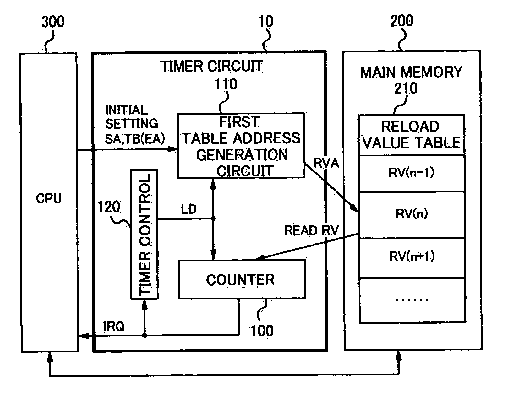
[0033]FIG. 1 is a diagram illustrating a configuration of a timer / counter circuit 10 (hereinafter referred to as “timer circuit”) included in or externally attached to a microcomputer according to a first embodiment of the present invention.

[0034] The timer circuit 10 includes a counter 100, a first table address generation circuit 110, and a timer control circuit 120, and is operated by being connected to a main memory 200 and a CPU 300 (“processor” according to the present invention).

[0035] The counter 100 is configured with a down counter which carries out down-count with a reload value RV as a count initial value and outputs an interrupt request signal IRQ and other status flags when the count value CV has become ‘0’. The counter 100 may include also an up counter or an up / down counter instead of the down counter. For example, in thee case of the up counter, an embodiment may be so constituted that up-count is carried out from ‘0’ with the reload value RV as a count final valu...

second embodiment

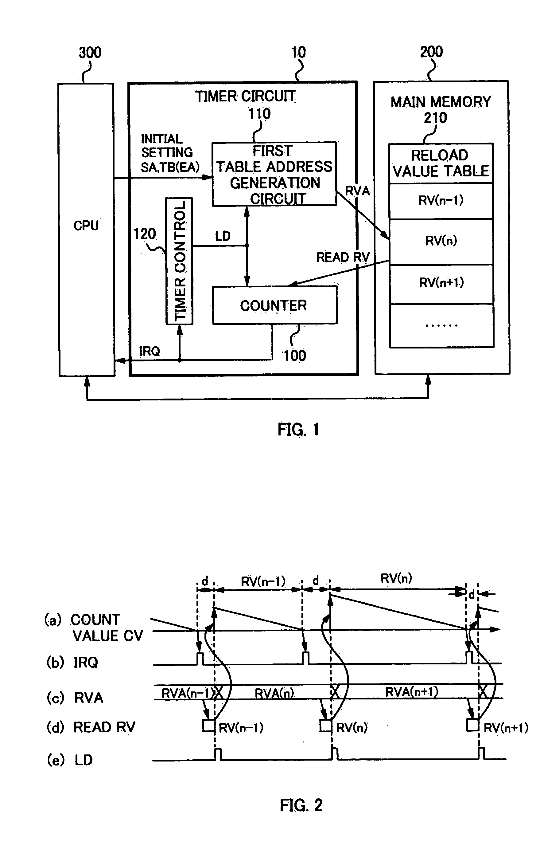
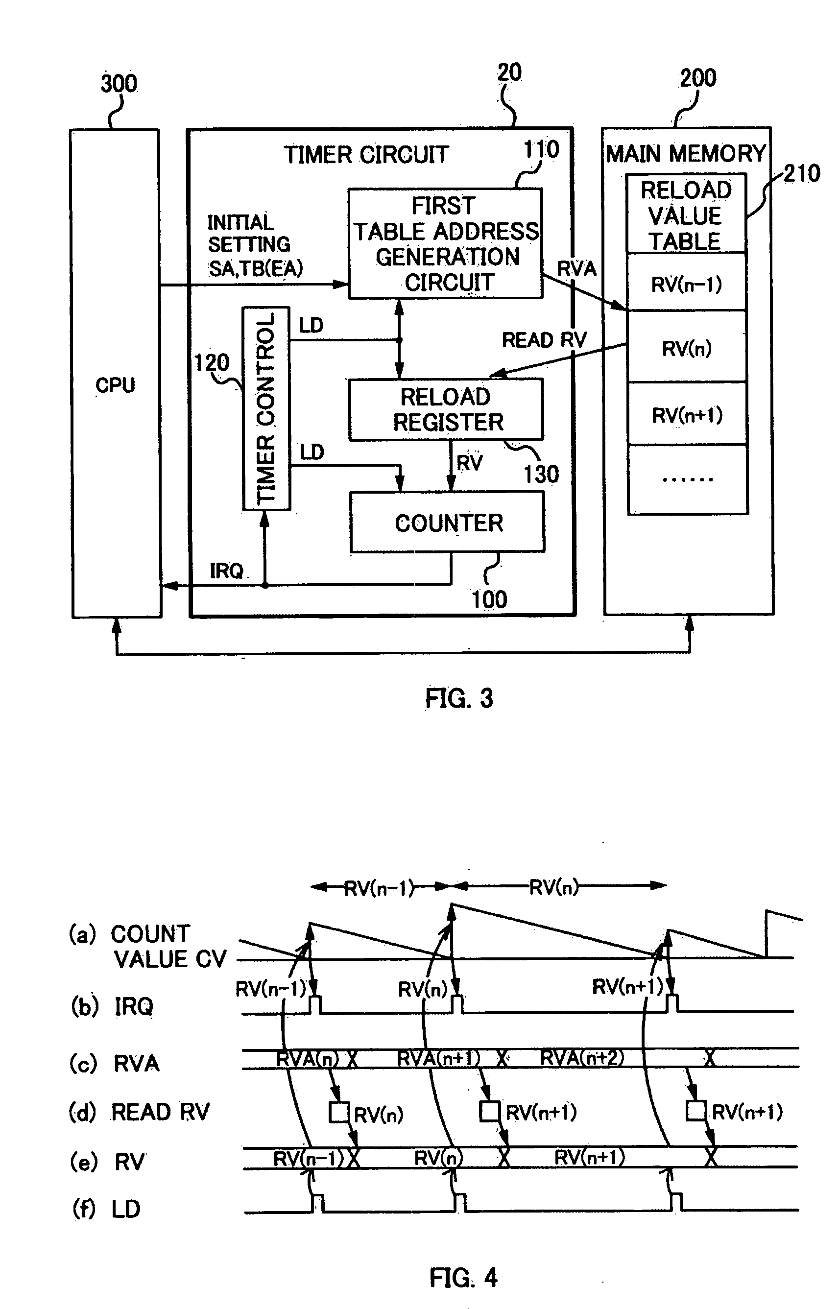
[0048]FIG. 3 is a diagram illustrating a configuration of a timer circuit 20 according to a second embodiment of the present invention.

[0049] A difference between the second embodiment and the first embodiment according to the present invention is that the timer circuit 20 is provided with a reload register 130 for temporarily storing the reload value RV read out from the main memory 200 before setting in the counter 100.

[0050] That is, in the first embodiment according to the present invention, as shown in FIG. 2(a), after the counter 100 generates the interrupt request signal IRQ, since the CPU 300 and other DMA and the like access the main memory 200 and the subsequent reload value RV can not be read out from the main memory without delay, there is a possibility that a waiting time d (overhead) might occur at the start of the count operation based on the new reload value RV. Then, by further providing the reload register 130, the timer circuit 20 attempts to solve the waiting t...

third embodiment

[0056]FIG. 5 is a diagram illustrating a configuration of a timer circuit 30 according to a third embodiment of the present invention.

[0057] A difference between the third embodiment and the first and second embodiments according to the present invention is that a reload value address table 220 in which a plurality of reload value addresses RVA are arranged in the predetermined order of entry (order of read-out) is provided in the main memory 200. The reload value address table 220 may be newly set in the main memory 200 for the present invention, but it is preferable that a system management table prepared in advance by a real-time OS for a microcomputer (for example, μITRON, incorporated Linux and the like) for task management etc. is utilized effectively.

[0058] In the third embodiment according to the present invention, the timer circuit 30 is provided with a second table address generation circuit 140 and a reload value address register 145 corresponding to the reload value ad...


PUM


Abstract

A timer circuit for setting a reload value according to a time to be measured and carrying out count operation based on the set reload value, comprising: a memory configured to store a plurality of reload values; a reload value address generation circuit configured to generate a reload value address indicating a storage location of each of the plurality of reload values in the memory; a counter configured to carry out count operation based on the reload value read out from the memory referring to a reload value address generated in the reload value address generation circuit; and a timer control circuit configured to control update of the reload value address in the reload value address generation circuit and read-out of the reload value from the memory to the counter.

Description

CROSS-REFERENCE TO RELATED APPLICATION [0001] This application claims the benefit of priority to Japanese Patent Application No. 2006-270984, filed Oct. 2, 2006, of which full contents are incorporated herein by reference. BACKGROUND OF THE INVENTION [0002] 1. Field of the Invention [0003] The present invention relates to a timer circuit and a signal processing circuit provided therewith. [0004] 2. Description of the Related Art [0005] Timer / counter circuits, which measure a predetermined period by counting edges of a clock signal, (hereinafter referred to as “timer circuit”) are variously used for generating various kinds of timing in a signal processing circuit in a microcomputer, DSP and the like. For example, in a microcomputer, a timer circuit is usually provided for timer interruption, which is a type of hardware interruption. [0006]FIG. 12 is a diagram illustrating a configuration of a timer circuit included in a conventional microcomputer, and FIG. 13 is a diagram illustrati...

Claims


Application Information

Patent Timeline
Patent Type & Authority Applications(United States)
IPC IPC(8): G06M3/02
CPCG06F1/14
Inventor TOMISAWA, SHIN-ICHIRO
Owner SANYO ELECTRIC CO LTD
Why Eureka
Try Eureka