
Socket for test

a technology for sockets and test tubes, applied in the field of sockets for test, can solve the problems of difficult manufacturing of metal tubes b>, difficult to achieve optimal shape, and increase the cost of interposing metal tubes, and achieve the effect of low-cost components and easy manufacturing

Inactive Publication Date: 2008-04-17
YOKOWO CO LTD
View PDF2 Cites 66 Cited by
  • Summary
  • Abstract
  • Description
  • Claims
  • Application Information

AI Technical Summary

Benefits of technology

[0005] It is therefore an object of the invention to provide a socket for test which is so constructed that electrical connection can be reliably obtained between a probe for grounding and a metal block, while respective probes are supported by the metal block, and that the socket can be easily manufactured employing low-cost components.

Problems solved by technology

Therefore, it is difficult to manufacture the metal tube 97 in an optimal shape with high yield, even with such precision as having tolerance of ±0.01 mm.
Further, since the metal tube 97 has the bell-shape, the metal tube 97 can be removed only from the opposite side, once it has been inserted into the through hole in the metal block 2, and there has been a problem that it takes a number of manufacturing steps and an increase of cost to interpose the metal tube 97.

Method used


Image

  • Socket for test
  • Socket for test
  • Socket for test

Examples


Embodiment Construction

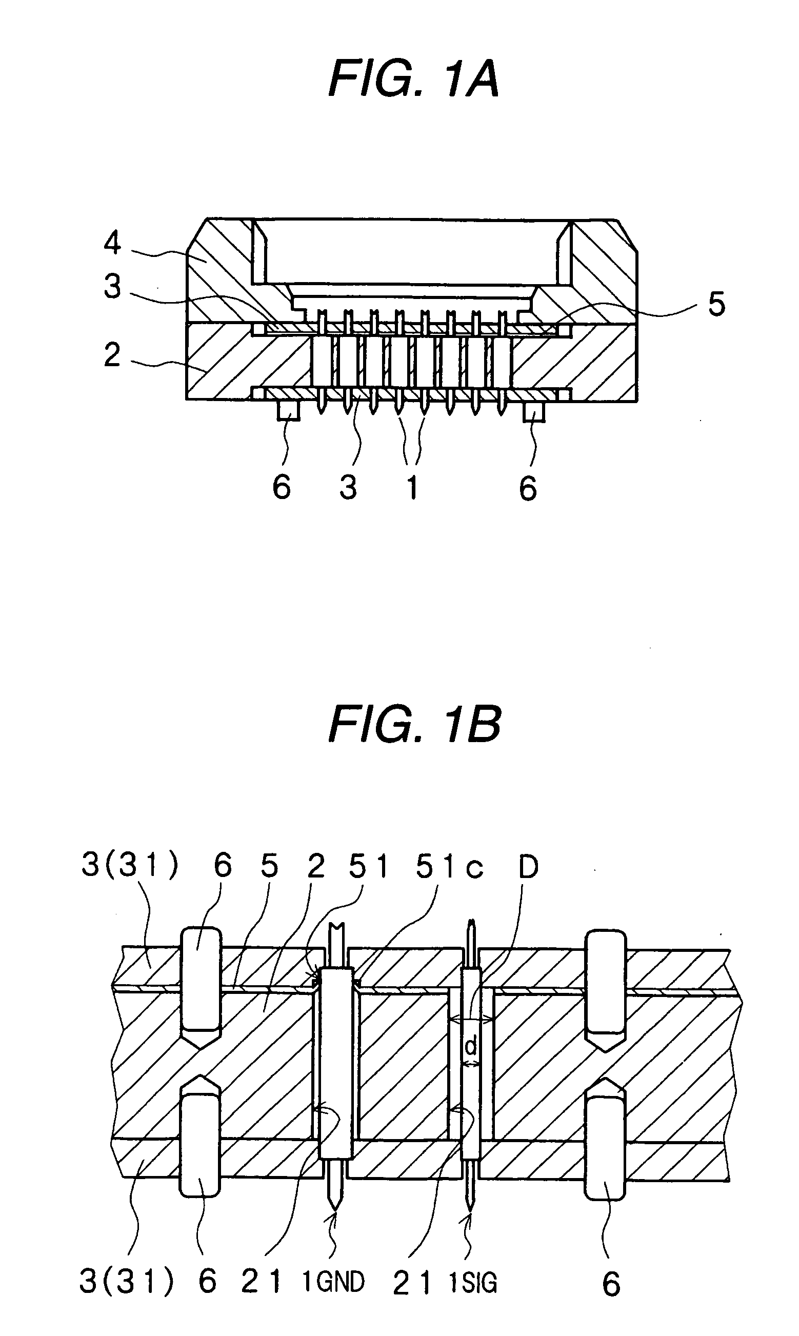
[0023] Now, referring to the drawings, the socket for test according to the invention will be described. In FIGS. 1A and 1B, there are shown a sectional view for explaining the socket for test in an embodiment according to the invention, and an enlarged sectional view for explaining a part of the same. In FIGS. 2A to 2C, there are shown a plan view for explaining a part of a ground plate, and a plan view for explaining a part of a metal block in which probes 1 are inserted, and a perspective view for explaining a part of the metal block 2 in a state where the ground plate 5 is mounted on a surface of the metal block (in a state where a fixing plate 3 is omitted).

[0024] Herein, the probe means a connecting pin which interconnects a wiring terminal on a wiring board with an electrode terminal (a lead terminal) of a device to be tested, including both a contact probe of a type that a distal end of the connecting pin is movable, and a pin having a fixed length but not movable. The cont...


PUM


Abstract

A socket for test includes: a support block, having a first face and a second face different from the first face, and formed with through holes; probes, provided in the through holes, and electrically connected to terminals of a device to be tested provided on a side of the first face and to terminals connected to a testing apparatus provided on a side of the second face, the probes including a first probe for grounding and a second probe different from the first probe; and a first plate member, formed with a first hole corresponding to the first probe and having a smaller diameter than a diameter of the first probe, slots radially extended from the first hole, and a second hole corresponding to the second probe and having a larger diameter than a diameter of the second probe, the first plate member being in electrical contact with the support block.

Description

BACKGROUND OF THE INVENTION [0001] The present invention relates to a socket for test which interconnects electrode terminals (lead terminals) of a device to be tested and wiring terminals to be connected to a testing apparatus by means of probes which are supported by a metal block, for the purpose of testing electrical performance of the device to be tested such as an IC, before the device is actually assembled into a circuit. More particularly, the invention relates to the socket for test having improved contact structure in a probe for grounding, which is one of the probes, by which structure the probe for grounding can be easily assembled, while it is in reliable electrical contact with the metal block. [0002] Test for testing performance of a device (an object to be tested) such as a semiconductor wafer, an IC or a module, by inputting an electric signal to the device, has been generally conducted. In case of conducting such test of electrical performance of the device, there ...

Claims


Application Information

Patent Timeline
IPC IPC(8): G01R1/04G01R31/26
CPCG01R1/0466G01R1/045G01R1/07314G01R1/06772H01R33/76
Inventor YOSHIDA, TAKUTO
Owner YOKOWO CO LTD
Learn More