
Battery Including a Fluid Manager Mounted Internal to Cell

a fluid manager and battery technology, applied in the field of fluid regulating systems, can solve the problems of limited discharge rate, reduced material content, and reduced material content of oxygen reduction electrodes,

Active Publication Date: 2008-04-10
ENERGIZER BRANDS
View PDF45 Cites 26 Cited by
  • Summary
  • Abstract
  • Description
  • Claims
  • Application Information

AI Technical Summary

Benefits of technology

The present invention provides a battery with a fluid regulating system that includes a valve for controlling the rate at which fluid enters the battery. The valve has a plate with at least one aperture that is pressed against the inside surface of the battery housing by a gasket. This design helps to control the flow of fluid and ensures consistent performance of the battery.

Problems solved by technology

However, some materials used in oxygen reduction electrodes are not true catalysts because they can be at least partially reduced, particularly during periods of relatively high rate of discharge.
A disadvantage of these cells is that the maximum discharge rates they are capable of can be limited by the rate at which oxygen can enter the oxygen reduction electrode.
However, changing the diffusion rate of one of these gases generally affects the others as well.
Even when efforts have been made to balance the need for a high rate of oxygen diffusion and low rates of CO2 and water diffusion, there has been only limited success.
To provide an increase in air flow into the cell only during periods of high rate discharge, fans have been used to force air into cells (e.g., U.S. Pat. No. 6,500,575), but fans and controls for them can add cost and complexity to manufacturing, and fans, even micro fans, can take up valuable volume within individual cells, multiple cell battery packs and devices.
However, the pressure differential may be small and can be affected by the atmospheric conditions outside the battery.

Method used


Image

  • Battery Including a Fluid Manager Mounted Internal to Cell
  • Battery Including a Fluid Manager Mounted Internal to Cell
  • Battery Including a Fluid Manager Mounted Internal to Cell

Examples


Embodiment Construction

[0075] Embodiments of this invention include a battery that includes an electrochemical cell that utilizes a fluid (such as oxygen or another gas) from outside the cell as an active material for one of the electrodes. The cell has a fluid consuming electrode, such as an oxygen reduction electrode. The cell can be an air-depolarized cell, an air-assisted cell, or a fuel cell. The battery also has a fluid regulating system for adjusting the rate of passage of fluid to the fluid consuming electrode (e.g., the air electrodes in air-depolarized and air-assisted cells) to provide a sufficient amount of the fluid from outside the cell for discharge of the cell at high rate or high power, while minimizing entry of fluids into the fluid consuming electrode and water gain or loss into or from the cell during periods of low rate or no discharge.

[0076] Preferably the fluid regulating system will have a fast response to changes in cell potential, a long cycle lifetime, a low operating voltage t...


PUM

PropertyMeasurementUnit
diameteraaaaaaaaaa
temperatureaaaaaaaaaa

Abstract

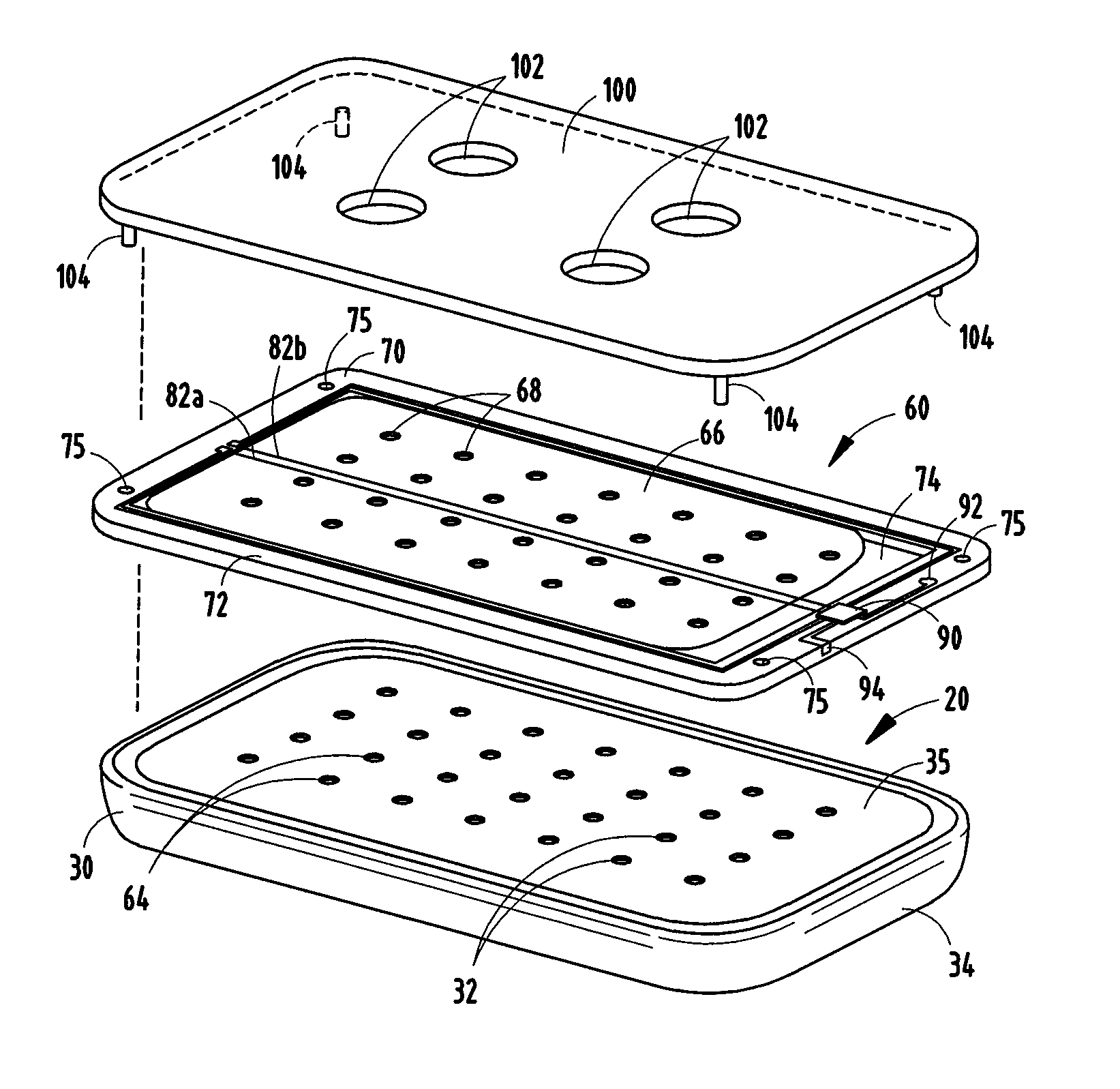
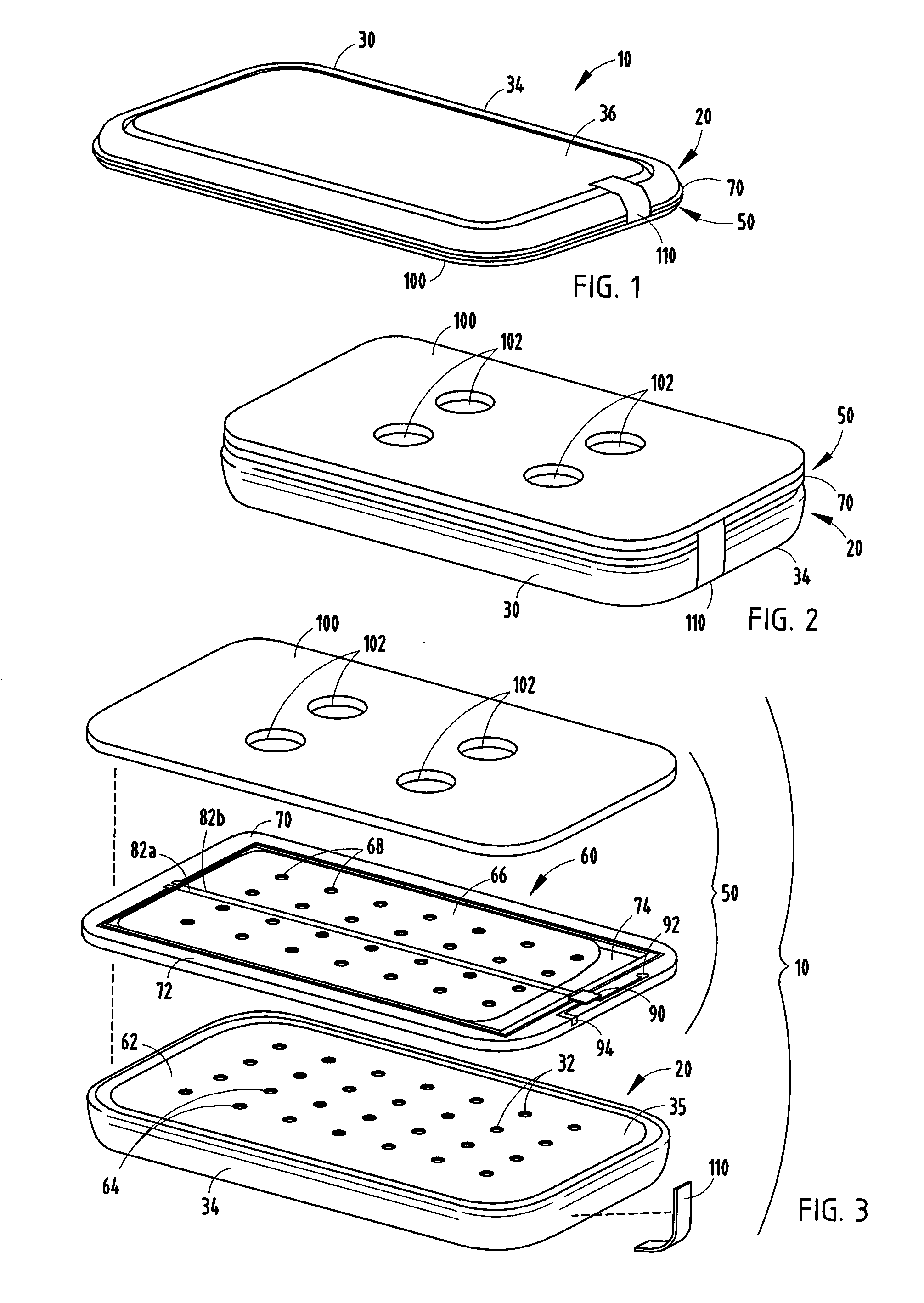
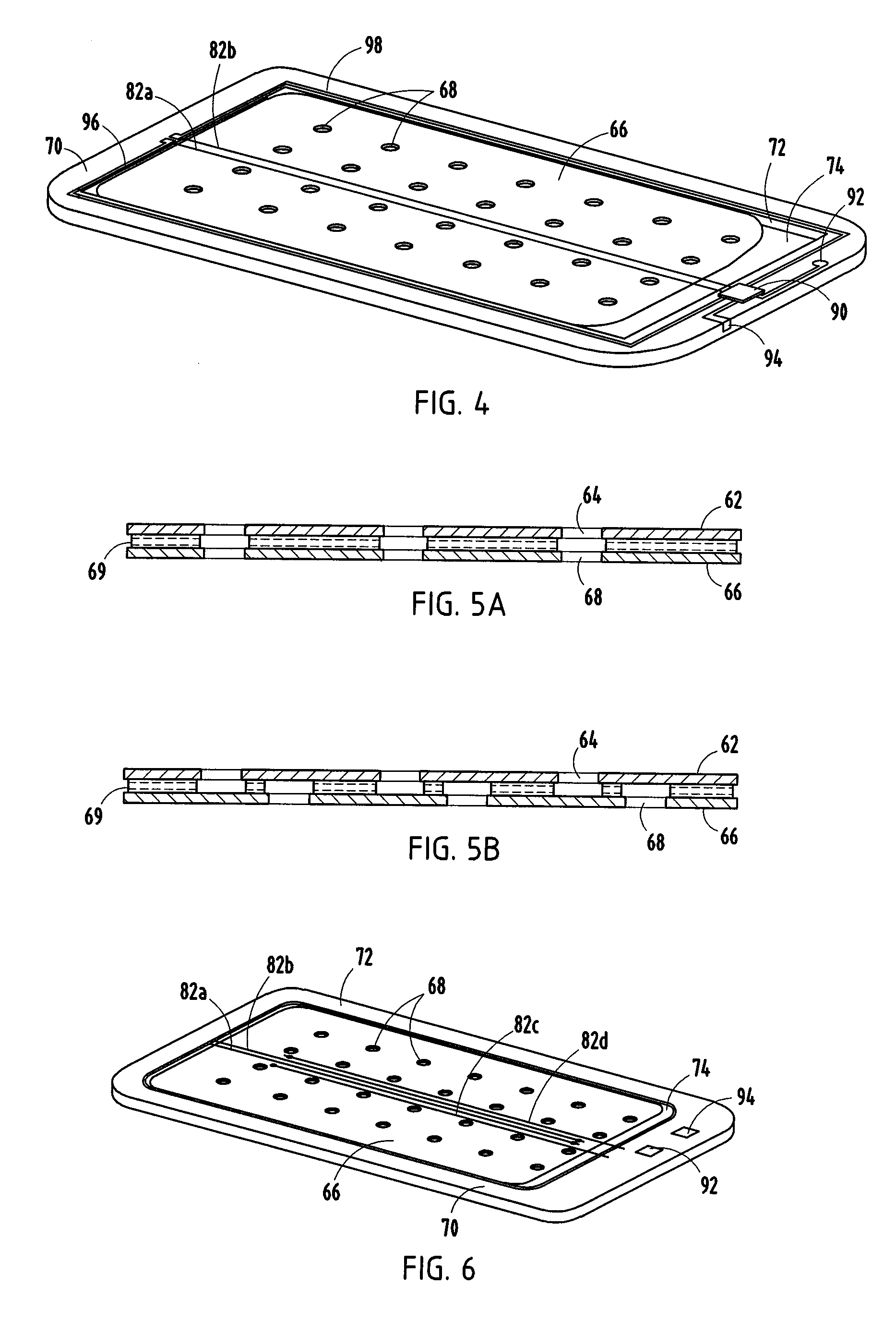
A fluid consuming battery (10) is provided with a fluid regulating system (50) for regulating fluid entry into the battery. The battery (10) includes a fluid consuming cell (20) having a cell housing with fluid entry ports for the passage of a fluid into the cell housing. A first fluid consuming electrode and a second electrode are disposed within the cell housing. The fluid regulating system (50) includes a valve having a moving plate (66) disposed adjacent to a fixed plate (62). The moving plate and fixed plate both have fluid entry ports (68, 64) that align in an open valve position and are misaligned in a closed valve position. The fluid regulating system (50) also includes an actuator that may include one or more shape memory alloy (SMA) components (82a, 82b) for moving the moving plate (66) relative to the fixed plate (62) to open and close the valve.

Description

CROSS-REFERENCE TO RELATED APPLICATIONS [0001] This application claims the benefit of U.S. Provisional Application No. 60 / 790,876, filed on Apr. 11, 2006, U.S. Provisional Application No. 60 / 817,199, filed on Jun. 28, 2006, and U.S. Provisional Application No. 60 / 860,175, filed on Nov. 20, 2006, the entire disclosures of each of the above applications are incorporated herein by reference.BACKGROUND OF THE INVENTION [0002] This invention relates to fluid regulating systems for controlling the rate of entry of fluids, such as gases, into and out of electrochemical batteries and cells with fluid consuming electrodes, and to the batteries and cells in which such fluid regulating systems are used, particularly air-depolarized, air-assisted and fuel cells and batteries. [0003] Electrochemical battery cells that use a fluid, such as oxygen and other gases, from outside the cell as an active material to produce electrical energy, such as air-depolarized, air-assisted and fuel cell battery c...

Claims


Application Information

Patent Timeline
Patent Type & Authority Applications(United States)
IPC IPC(8): H01M2/38H01M50/103H01M50/77
CPCH01M2/0202H01M2/0207Y10T29/49108H01M12/06H01M2002/0205H01M2/1229Y02E60/10Y02E60/50H01M50/325H01M50/103H01M8/04089H01M8/04753H01M50/1385H01M50/394
Inventor LANGAN, RICHARD A.BURSTALL, OLIVER W.
Owner ENERGIZER BRANDS
Learn More