
Rotating Dispenser Head with Locking and Venting Closure Connector for an Air Foaming Pump Dispenser

a dispenser and valve connector technology, applied in the direction of liquid handling, closure using stoppers, instruments, etc., can solve the problems of inward collapsing of the bottle side wall, more component parts, and a complex assembly of the dispenser, so as to minimize the number of component parts and simplify the dispenser assembly.

Active Publication Date: 2008-04-10
SILGAN DISPENSING SYST CORP
View PDF17 Cites 30 Cited by
  • Summary
  • Abstract
  • Description
  • Claims
  • Application Information

AI Technical Summary

Benefits of technology

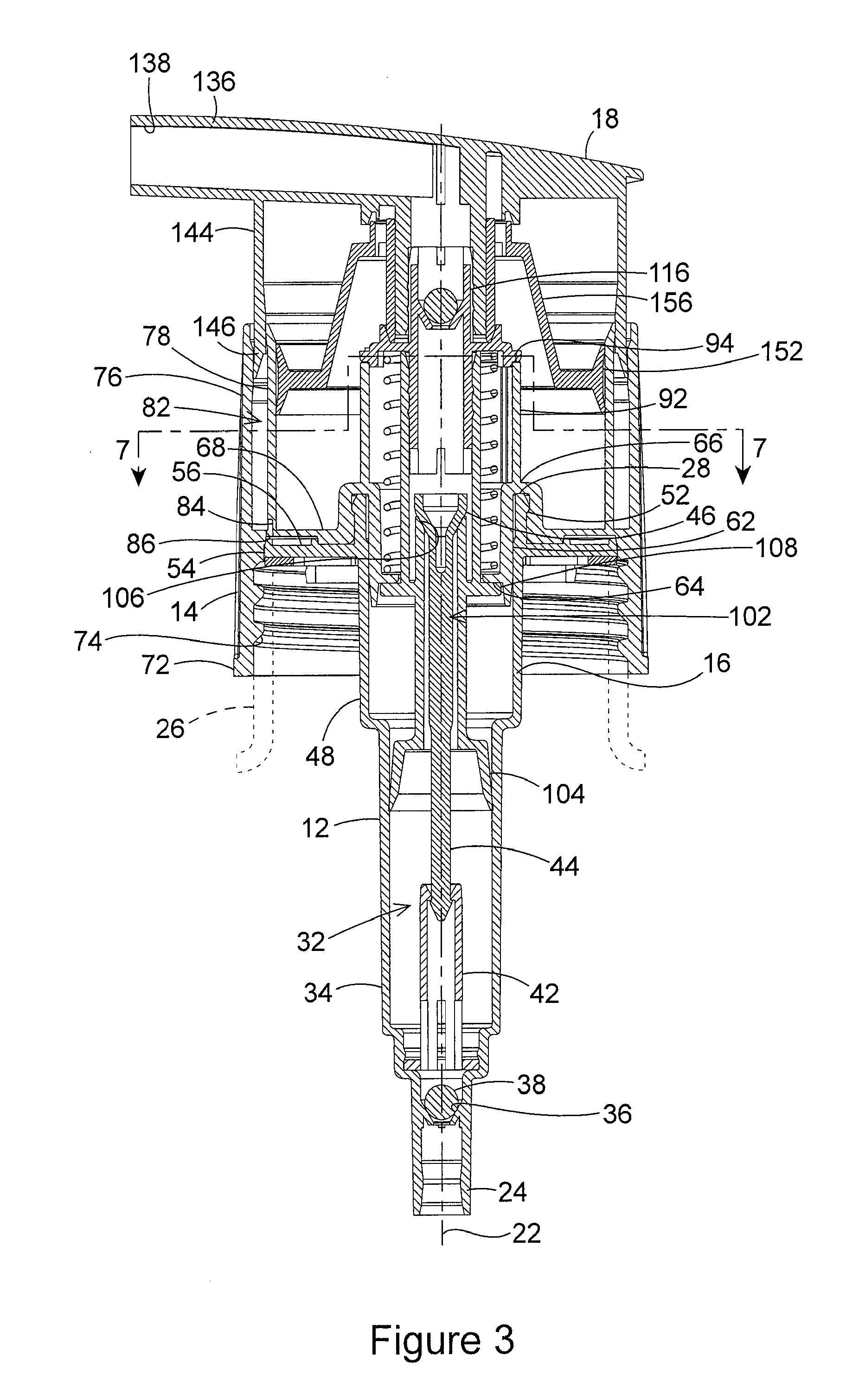
[0013]The manually operated, vertically reciprocating air foaming pump dispenser of the invention provides a unique dispenser construction that includes both liquid and air pumps and also provides a venting features and a locking feature while minimizing the number of component parts and the complexity of the dispenser assembly.
[0016]A dip tube extends downwardly from the bottom of the pump housing and communicates the dispenser with liquid in a bottle to which the dispenser is attached. A ball check valve is positioned in the pump housing between the dip tube and pump chamber. The ball valve controls the flow of liquid into the pump chamber, and prevents the reverse flow of liquid.
[0019]A ball check valve is positioned in the liquid discharge passage adjacent the top of the plunger. The ball valve controls the flow of liquid from the pump chamber through the plunger, and prevent the reverse flow of liquid.
[0023]A dispensing head is mounted on the top of the pump plunger. The dispensing head contains a spout having an outlet passage that communicates with the liquid discharge passage of the plunger. The dispensing head also has a cylindrical sleeve that extends downwardly into the cylindrical empty space between the closure connector exterior wall and the air pump chamber wall. The thickness of the sleeve increases as it extends downwardly. The dimensions of the dispensing head sleeve cause a downward portion of the sleeve to engage in a sealing engagement between the closure connector exterior wall and the air pump chamber wall when the plunger is moved upward to the charge position of the pump plunger. This seals closed the vent air flow path through the pump dispenser. The dimensions of the dispensing head sleeve also allow the sleeve to disengage from the closure connector exterior wall and the air pump chamber wall when the pump plunger is moved downward to the discharge position of the pump plunger. This opens the air flow path through the pump dispenser.
[0024]Thus, the pump dispenser of the invention comprises both a liquid pump and an air pump that mix liquid and air pumped through the dispenser to create a foam dispensed by the dispenser. In addition, the novel construction of the pump dispenser incorporates the closure connector with a venting feature and a lock feature of the dispenser, thereby reducing the number of component parts of the dispenser and simplifying the dispenser construction.

Problems solved by technology

The increasing vacuum in the interior of the bottle could also possibly result in the inwardly collapsing of the bottle side walls.
All of the above-described features that are often included in the typical construction of a manually operated, vertically reciprocated pump dispenser add to the number of component parts of the dispenser and add to the complexity of the assembly of the dispenser.
Dispensers of this type that pump both liquid and air have even more component parts and an even more complex assembly than dispensers that pump only liquid.
To provide a dispenser of this type with a venting feature and a locking feature would even further increase the number of component parts and the complexity of the assembly of the dispenser.

Method used


Image

  • Rotating Dispenser Head with Locking and Venting Closure Connector for an Air Foaming Pump Dispenser
  • Rotating Dispenser Head with Locking and Venting Closure Connector for an Air Foaming Pump Dispenser
  • Rotating Dispenser Head with Locking and Venting Closure Connector for an Air Foaming Pump Dispenser

Examples


Embodiment Construction

[0033]The basic component parts of the pump dispenser that comprise the novel features of the invention are the pump housing 12, the closure connector 14, the pump plunger 16 and the dispenser head 18. These four basic component parts, as well as most of the other component parts of the dispenser to be described, are constructed of a plastic material typically used in the construction of pump dispensers of this type. The exceptions are the coil spring of the dispenser and a pair of ball valves of the dispenser, which could be constructed of plastic, but are usually constructed of metal.

[0034]The pump housing 12 has a tubular length with a hollow center bore having a center axis 22. The length of the pump housing 12 extends from a dip tube connector 24 at the bottom of the pump housing to an opposite top end 28 of the pump housing that surrounds a top opening into the pump housing. The dip tube connector 24 connects to a dip tube (not shown) that extends into the interior of a bottle...


PUM


Abstract

A manually operated, vertically reciprocating liquid pump dispenser is removably connectable to a bottle containing liquid and simultaneously pumps liquid from the bottle and air from the exterior environment of the dispenser and mixes the liquid with the air to produce a foam that is dispensed from the dispenser. The dispenser includes a closure connector that provides a mechanism for venting the interior of the bottle to the exterior environment of the dispenser while avoiding leakage of the liquid from the bottle, and also incorporates a mechanism for locking the dispenser to prevent unintended pumping of liquid from the bottle.

Description

BACKGROUND OF THE INVENTION [0001](1) Field of the Invention[0002]The present invention pertains to a manually operated reciprocating liquid pump dispenser that is removably connectable to a bottle containing a liquid. Manual operation of the dispenser simultaneously pumps the liquid from the bottle and pumps air from the exterior environment of the dispenser, mixes the liquid with the air to produce a foam, and dispenses the foam from the dispenser. More specifically, the pump dispenser of the invention includes a closure connector that provides a mechanism for venting the interior of the bottle to the exterior environment of the pump dispenser while avoiding leakage of the liquid from the bottle, and also incorporates a mechanism for locking the pump dispenser to prevent unintended pumping of the liquid from the bottle.[0003](2) Description of the Related Art[0004]Manually operated, vertically reciprocated pump dispensers are those types of dispensers that are typically oriented v...

Claims


Application Information

Patent Timeline
Patent Type & Authority Applications(United States)
IPC IPC(8): B67D5/00B67D5/58B67D7/76B67D99/00
CPCB05B7/0037B05B11/0016B05B11/3087B05B11/3059B05B11/3001B05B11/0044B05B11/1059B05B11/1001B05B11/1087
Inventor NELSON, PHILIP L.
Owner SILGAN DISPENSING SYST CORP
Learn More