
Parallel bit test device and method using error correcting code

a bit test and error correction technology, applied in error detection/correction, instruments, computing, etc., can solve the problems of failure detection or correction of fail bits, failure detection of error correction devices, and deterioration of reliability and yield of semiconductor memory devices

Inactive Publication Date: 2008-04-03
SAMSUNG ELECTRONICS CO LTD
View PDF11 Cites 12 Cited by
  • Summary
  • Abstract
  • Description
  • Claims
  • Application Information

AI Technical Summary

Benefits of technology

[0035]A method of error detecting and correcting in a parallel bit test device according to an example embodiment may include comparing bits of an m-bit data signal with corresponding bits of expected data. The number of fail bits may be counted based on whether the bits of the m-bit data signal are the same as the corresponding bits of expected data. A correction control

Problems solved by technology

After manufacturing, the reliability and yield of semiconductor memory devices may deteriorate.
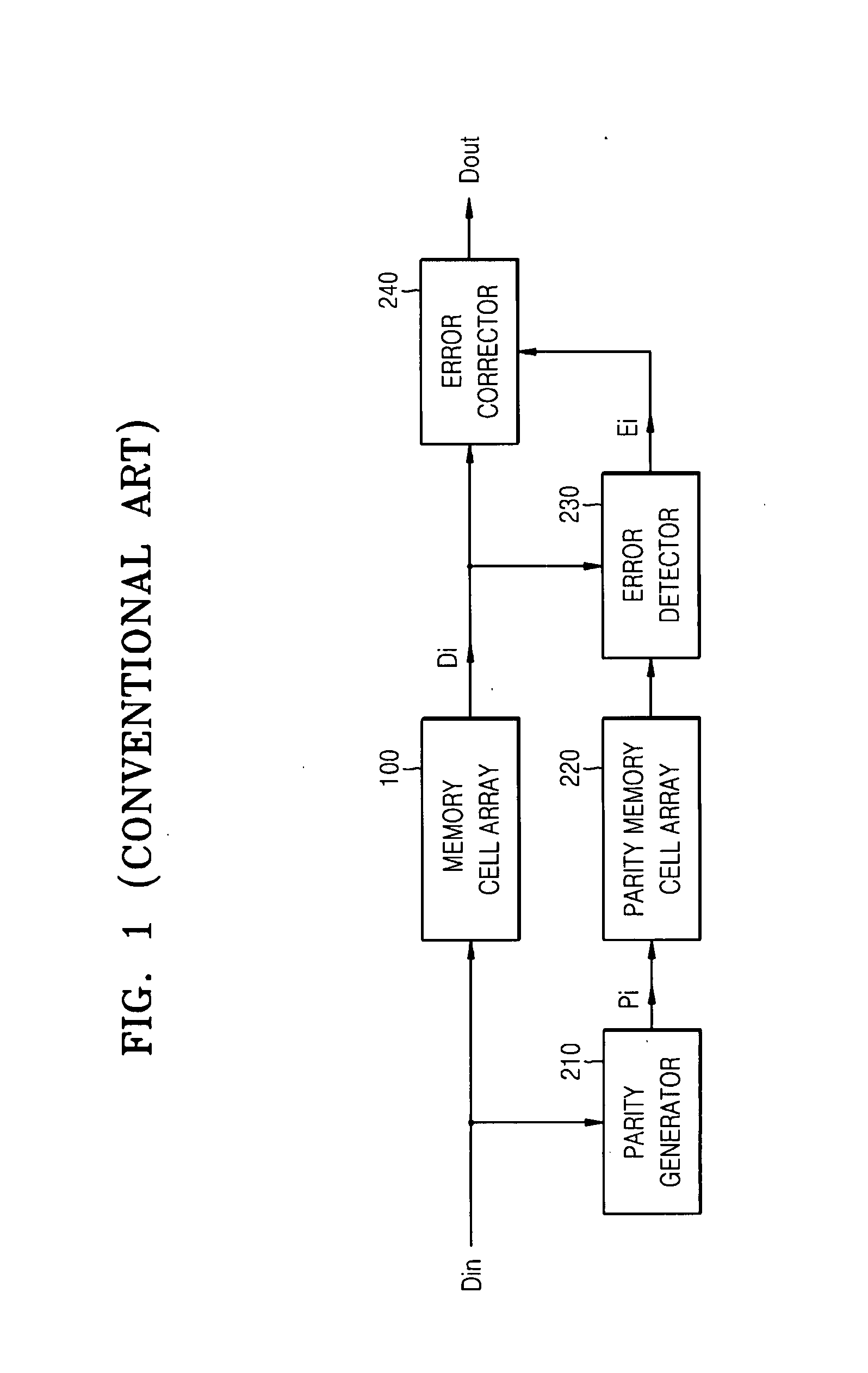
Conventional error correcting devices using Hamming code may detect one-bit errors of input data, however, when more than one fail bit is generated, the error correcting device may not be able to detect or correct the fail bits.
The conventional error correcting device illustrated in FIG. 1 may enable a data signal to be quickly compressed and tested, and may detect whether the compressed data signal has an error.
Accordingly, it may not be aware of the number of fail bits, and may detect only whether less than one bit error is generated.
However, the conventional parallel bit test device 300 may not be able to count the number of fail bits and detect the position of a fail bit.

Method used


Image

  • Parallel bit test device and method using error correcting code
  • Parallel bit test device and method using error correcting code
  • Parallel bit test device and method using error correcting code

Examples


Embodiment Construction

[0044]Detailed example embodiments are disclosed herein. However, specific structural and functional details disclosed herein are merely representative for purposes of describing example embodiments. Example embodiments may, however, be embodied in many alternate forms and should not be construed as limited to only the embodiments set forth herein.

[0045]Accordingly, while example embodiments are capable of various modifications and alternative forms, embodiments thereof are shown by way of example in the drawings and will herein be described in detail. It should be understood, however, that there is no intent to limit example embodiments to the particular forms disclosed, but to the contrary, example embodiments are to cover all modifications, equivalents, and alternatives failing within the scope of example embodiments. Like numbers refer to like elements throughout the description of the figures.

[0046]It will be understood that, although the terms first, second, etc. may be used h...


PUM


Abstract

Example embodiments are directed to a parallel bit test device and method using error correcting code. The parallel bit test device may include an error detecting and correcting unit configured to count the number of fail bits in an m-bit data signal, for example, by comparing bits of the m-bit data signal with corresponding bits of expected data, where m is a positive integer, and to output correction signals. The error detecting and correcting unit may be further configured to perform at least one logic operation on a correction control signal and comparison signals. The correction control signal may be generated in response to a test mode register set (TMRS) signal set and input by a user such that the logic level of the correction control signal may vary according to the counted number of fail bits. Each comparison signal may include information about a fail bit and the address of the fail bit.

Description

PRIORITY STATEMENT[0001]This application claims the benefit of Korean Patent Application No. 10-2006-0096136, filed on Sep. 29, 2006, in the Korean Intellectual Property Office, the entire contents of which are incorporated herein by reference.BACKGROUND[0002]1. Field[0003]Example embodiments are directed to a parallel bit test device, for example, a parallel bit test device using error correcting code (ECC).[0004]2. Description of the Related Art[0005]After manufacturing, the reliability and yield of semiconductor memory devices may deteriorate. Accordingly, an error recovery circuit may be used to detect, and possibly recover, defective memory cells.[0006]The error recovery circuit may include redundancy circuits with redundancy cells, which may be used to replace defective cells. The error recovery circuit may also include an error correcting circuit to generate a parity bit from input data, correct an error, and / or output error-corrected data.[0007]A semiconductor memory device ...

Claims


Application Information

Patent Timeline
IPC IPC(8): G06F11/00
CPCG06F11/1008G11C29/42
Inventor PARK, BOK-GUE
Owner SAMSUNG ELECTRONICS CO LTD
Learn More