
Low power vibration sensor and wireless transmitter system

a vibration sensor and wireless transmitter technology, applied in the field of low-power vibration sensors and wireless transmitter systems, can solve the problems of vibration monitoring systems that are not well suited to operation in a control protocol network, memory and bulk data transfer capabilities, and significant power supply requirements of vibration measurement devices

Active Publication Date: 2008-04-03
COMPUTATIONAL SYST
View PDF20 Cites 28 Cited by
  • Summary
  • Abstract
  • Description
  • Claims
  • Application Information

AI Technical Summary

Benefits of technology

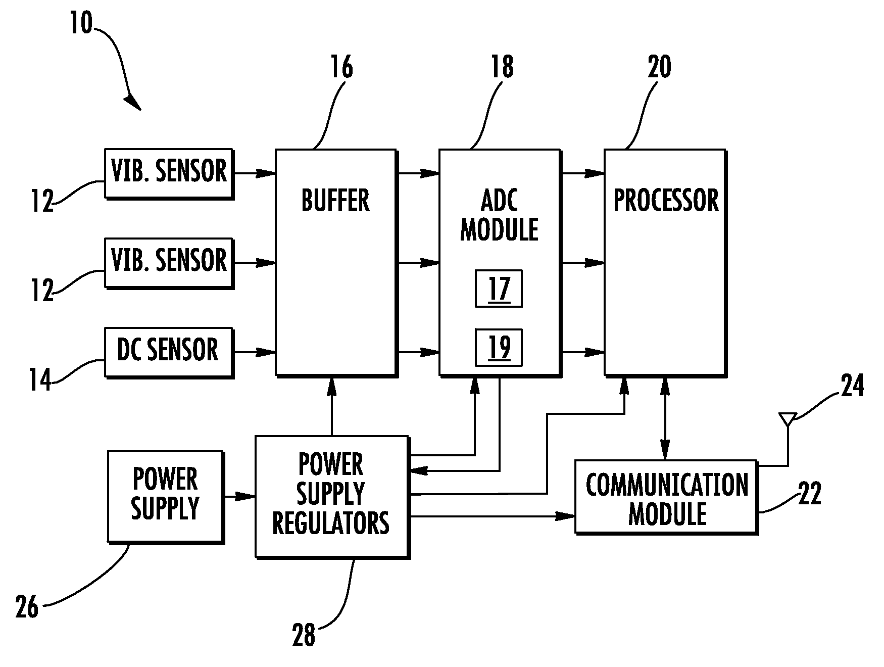
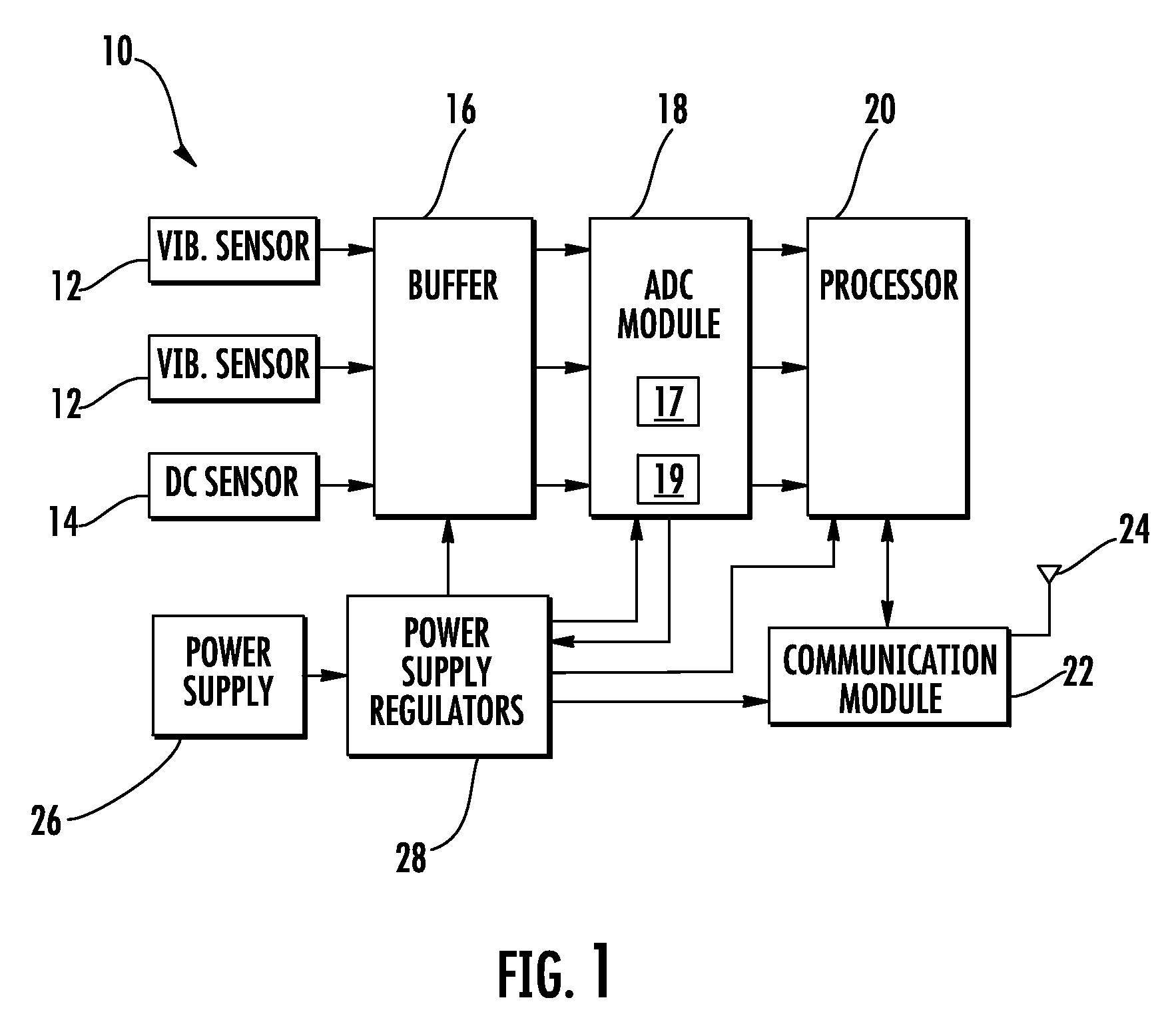
[0008]In other embodiments, the measurement instrument has a communication module and a communication processor controls the communication module. A communication power supply is connected to the communication processor and powers the communication processor, and an antenna is connected to the communication processor for wirelessly communicating the peak level and the overall RMS level to a control protocol network, such as a HART or a Fieldbus protocol network. Some embodiments of the instrument have multiple sensors for measuring vibration or relatively steady-state measurements such as temperature and pressure.

Problems solved by technology

Typically, vibration measurement devices require significant power supplies, memories and bulk data transfer capabilities.
Such bulk vibration waveforms typically require large memory capacities for storage.
Such vibration monitoring systems are not well suited for operation in a control protocol network.

Method used


Image

  • Low power vibration sensor and wireless transmitter system
  • Low power vibration sensor and wireless transmitter system
  • Low power vibration sensor and wireless transmitter system

Examples


Embodiment Construction

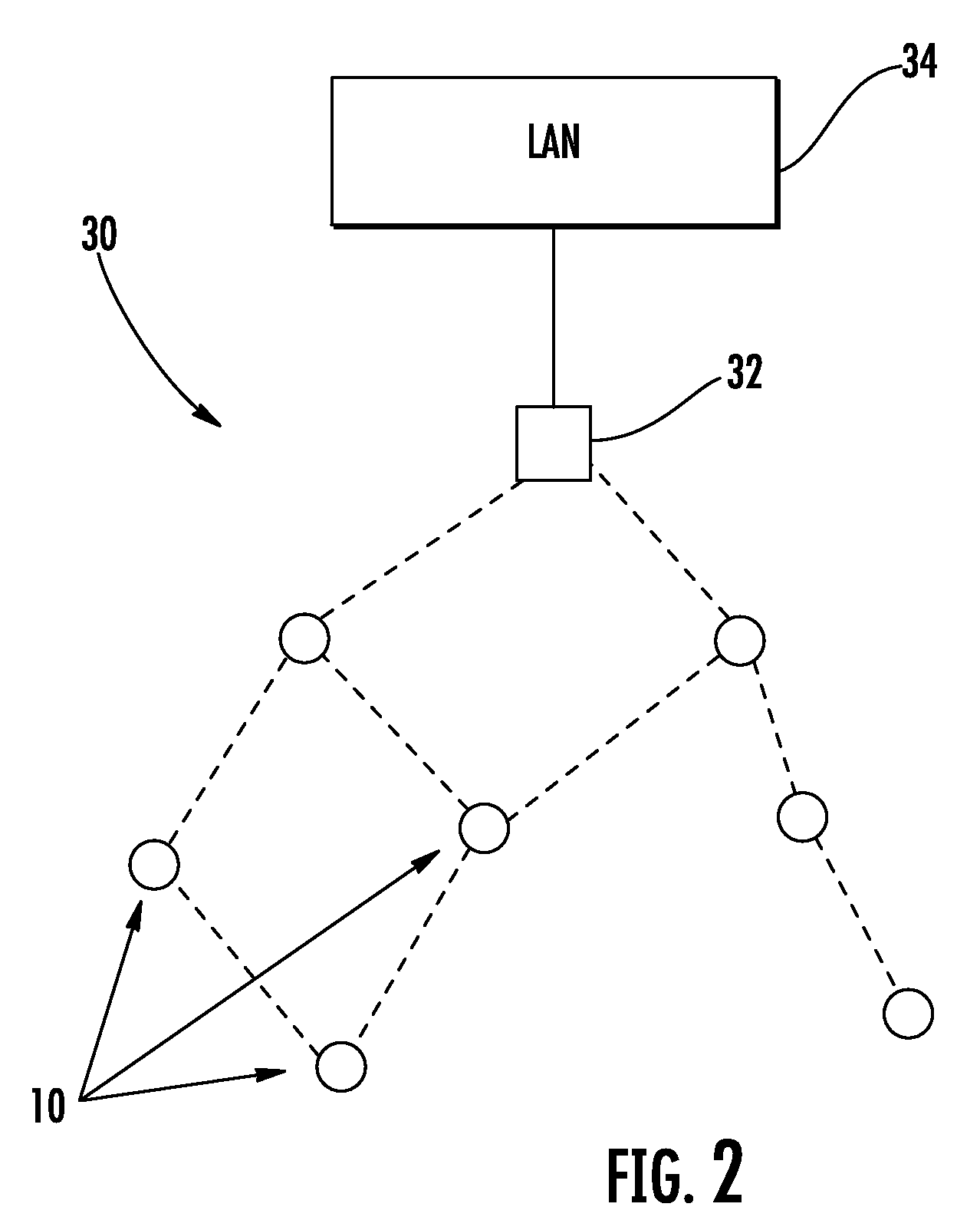
[0013]A low power vibration sensor and wireless transmitter system has one or more sensor inputs to measure conditions such as vibration on one or more sensors. Also, the system is capable of making one or more steady state or DC measurements of conditions such as temperature and pressure. In one embodiment, the system is self-contained without hardwired power or communication connections and communicates over a wireless, self-configuring daisy-chain network.

[0014]Generally, the signal generated from a vibration sensor, such as an industrial accelerometer has about a 100-120 dB dynamic range with a frequency bandwidth of about 20 kHz to about 30 kHz. To convert a signal generated by such an accelerometer into a digital signal capable of wireless transmission typically would require a 24-bit analog to digital converter sampling at about 100,000 to 200,000 samples per second. This system 10 breaks the signal into two pieces: a low frequency range (about 1-2 kHz) and a high frequency r...


PUM


Abstract

A low power vibration sensor and wireless transmitter system has one or more sensors that sense parameters of a machine including vibration and produces dynamic signals representing the sensed parameters. The system converts the signals to a digital format, digitally filters the signals, and processes the signals. A processor determines a plurality of levels, which represent the characteristics of the signal such as the peak value of a predetermined set of data points of the digital signal. Together, the levels comprise a PeakVue waveform. The processor determines the peak level value for the PeakVue waveform. Also, a true root-mean-square is calculated as the signal is received at the processor. The peak level and the RMS value are communicated wirelessly by a communication module to a control protocol network such as a daisy chain HART or Fieldbus protocol network. The system power supply and the communication module power supply are separate and allow for low power operation.

Description

CROSS REFERENCES TO RELATED APPLICATIONS[0001]This patent application claims priority from and is related to U.S. Provisional Patent Application Ser. No. 60 / 827,584 filed Sep. 29, 2006, entitled: “Vibration Transmitter Wireless Sensor”. This U.S. Provisional Patent Application is incorporated by reference in its entirety herein.FIELD[0002]This invention relates to the field of wireless vibration analysis. More particularly, this invention relates to a low power vibration sensor and wireless transmitter.BACKGROUND AND SUMMARY[0003]A parameter of a machine such as vibration may be measured and analyzed to monitor machine health. A parameter is used herein to refer to a physical property or other thing that is typically measurable such as vibration, pressure, voltage, current., temperature and the like. Vibration sensing instruments have been used to determine faults in machine function by detecting abnormalities in vibration, which correlates to different types of machine faults.[0004...

Claims


Application Information

Patent Timeline
Patent Type & Authority Applications(United States)
IPC IPC(8): G06F19/00G06F17/40
CPCG01H1/00G01H1/003G01H1/12G01M13/028G01M13/045G05B23/02G06F13/00
Inventor ROBINSON, JAMES C.BALDWIN, JOSEPH C.WALKER, JAMES W.CHILDRESS, WILLIAM E.
Owner COMPUTATIONAL SYST
Learn More