
Method for managing fuel cell power increases using air flow feedback delay

a fuel cell and air flow feedback technology, applied in the field of fuel cell system operation, can solve the problems of massive degradation, significant cell voltage drop, and huge drop in cathode stoichiometry at the reaction site, and achieve the effect of improving the stability of the stack

Active Publication Date: 2008-04-03
GM GLOBAL TECH OPERATIONS LLC
View PDF7 Cites 16 Cited by
  • Summary
  • Abstract
  • Description
  • Claims
  • Application Information

AI Technical Summary

Benefits of technology

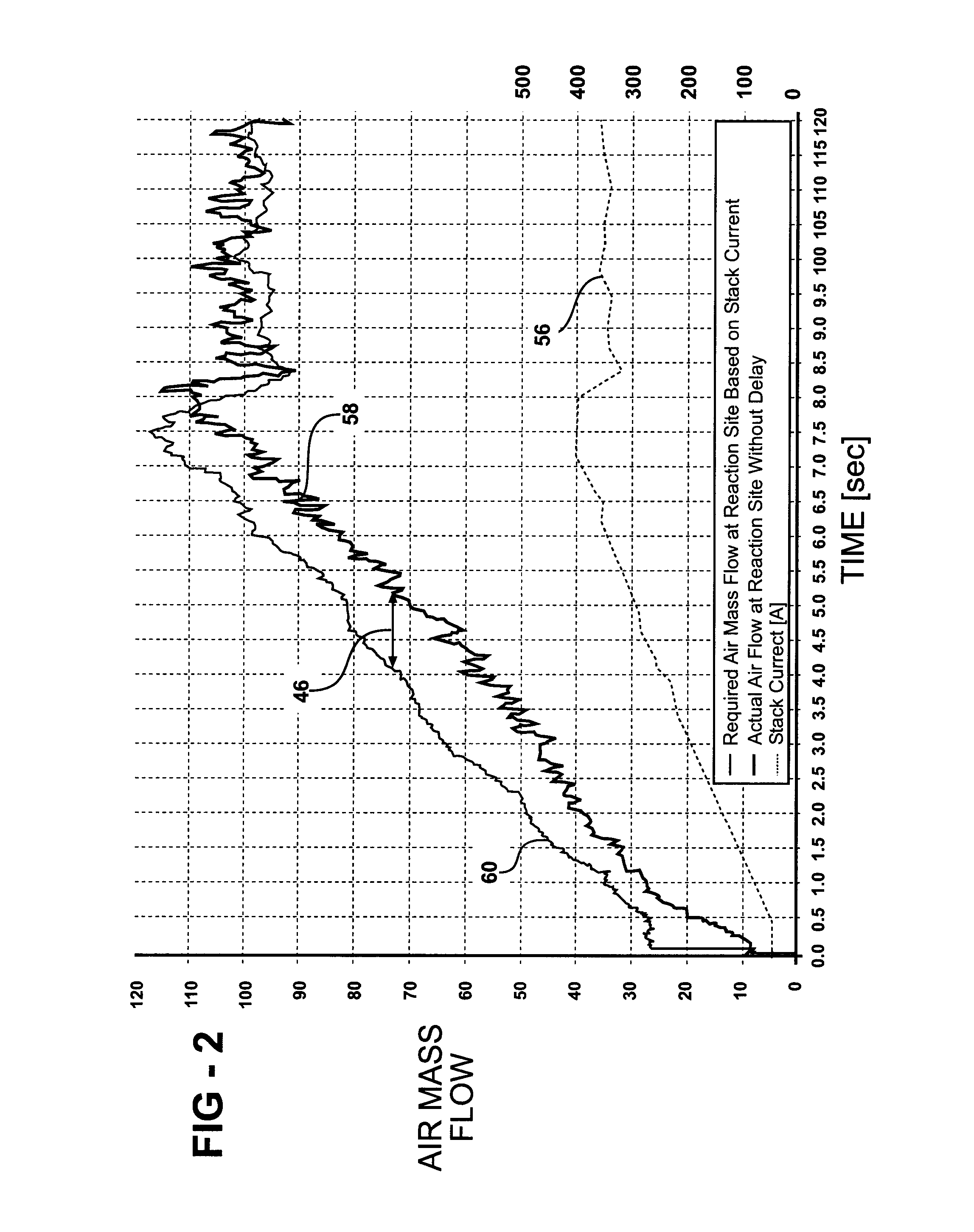
[0006]According to the present invention, a method of managing fuel cell power increases which would account for the volume and distance between the air mass flow sensor and the reaction site insuring the required air mass flow rate had reached the reaction site before the current is drawn from the fuel cell stack, has surprisingly been discovered. This method ensures that throughout an up-transient, the cathode stoichiometric requirement is always met at the site of the reaction. By ensuring this, stack stability is improved by preventing any one cell that is cathode stoichiometrically sensitive from losing voltage as a result of not having sufficient air. A secondary, but equally important, effect is the prevention of cathode starvation that leads to accelerated voltage degradation.

Problems solved by technology

The lack of air at the reaction site can cause the cathode stoichiometry at the reaction site to drop enormously, and lead to significant voltage drops in cells that are sensitive to low cathode stoichiometries.
The lowered cell voltages can at least cause the power management circuit to limit power output and could reverse (i.e. negative voltage) causing massive degradation.
The lack of air is particularly harmful on current draw up-transients.
The prior art systems do not take into account the distance and volume between where the air mass flow meter is taking the measurement and where the air-H2 reaction actually takes place.

Method used


Image

  • Method for managing fuel cell power increases using air flow feedback delay
  • Method for managing fuel cell power increases using air flow feedback delay
  • Method for managing fuel cell power increases using air flow feedback delay

Examples


Embodiment Construction

[0011]The following detailed description and appended drawings describe and illustrate various exemplary embodiments of the invention. The description and drawings serve to enable one skilled in the art to make and use the invention, and are not intended to limit the scope of the invention in any manner. In respect of the methods disclosed, the steps presented are exemplary in nature, and thus, the order of the steps is not necessary or critical.

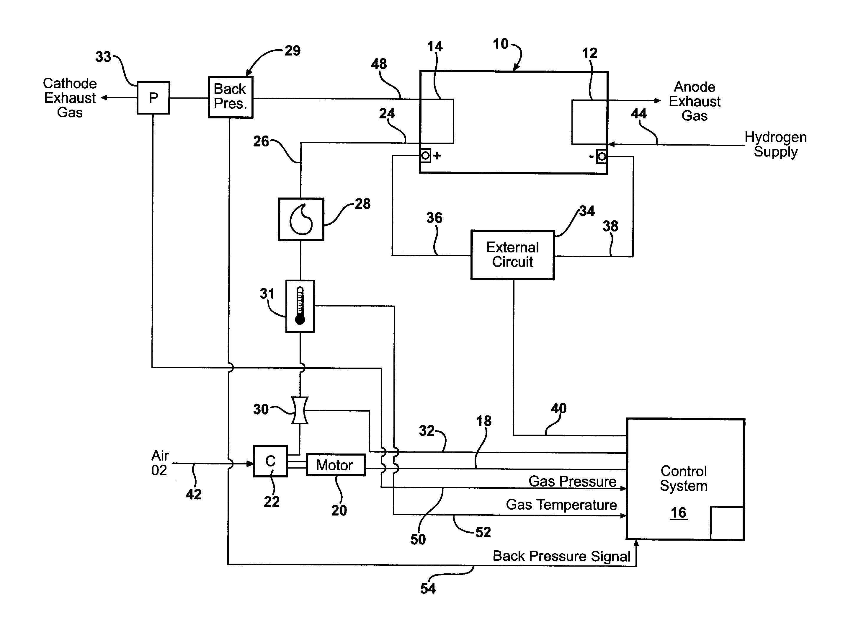
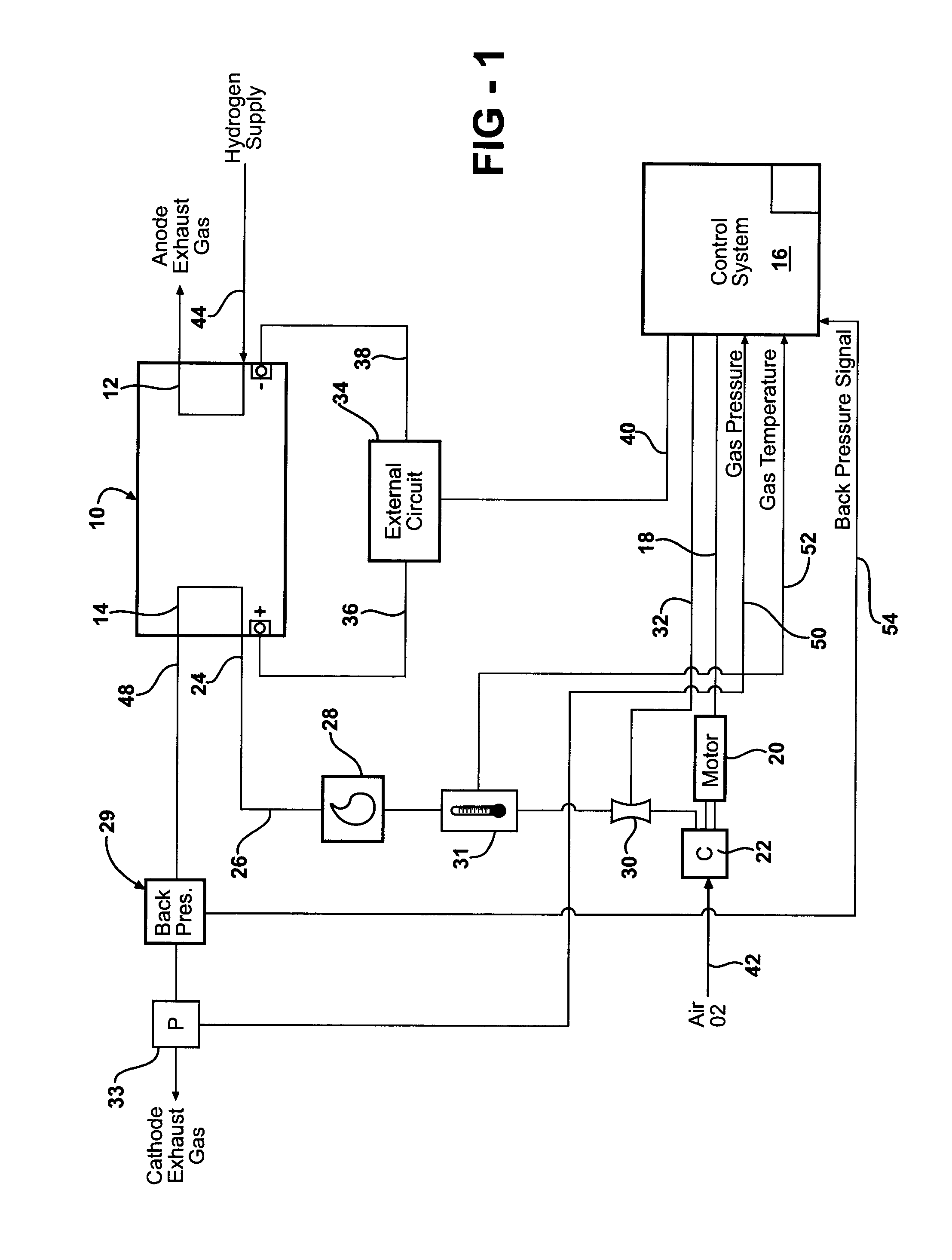
[0012]Referring now to FIG. 1, a basic layout of a fuel cell system with associated components is shown; in practice many variants are possible. A schematic representation of a fuel cell stack 10 integrated into a fuel cell system and consisting of a plurality of individual fuel cells which are connected electrically in series and / or in parallel is shown. The anode sides of all individual fuel cells of the fuel cell stack 10 are connected together in a manner commonly known in the art with the resulting anode side of the stack being designat...


PUM

PropertyMeasurementUnit
poweraaaaaaaaaa
air mass flow rateaaaaaaaaaa
gas pressureaaaaaaaaaa

Abstract

A method for managing fuel cell power increases in a fuel cell system using an air flow feedback delay. The method comprises the steps of determining a required air mass flow rate at a predetermined point in the fuel cell system, determining an actual air mass flow at a predetermined point in the fuel cell system, calculating an air flow feedback delay as a function of the required air mass flow rate and the actual air mass flow, and delaying an external circuit from increasing current draw from the fuel cell stack by the magnitude of the air flow feedback delay.

Description

FIELD OF THE INVENTION[0001]This invention relates to a method of operation for a fuel cell system. More particularly, the invention is directed to managing power increases in a hydrogen fuel cell system using an air mass flow feedback delay.BACKGROUND OF THE INVENTION[0002]In most modern fuel cell systems, a compressor provides compressed air to the fuel cell stack. Having sufficient air for the fuel cell reaction is extremely important and is characterized as “Cathode Stoichiometry” wherein a higher value (e.g. 5) is typically needed at low current densities and a lower value (e.g. 1.8) is typical at high current densities. In such systems it is necessary to have a means for sensing the air mass flow rate leaving the compressor and entering the fuel cell stack, such as an air mass flow sensor.[0003]A control system will typically take this flow information and change the speed of the compressor along with the position of a back pressure valve to achieve a desired air mass flow and...

Claims


Application Information

Patent Timeline
Patent Type & Authority Applications(United States)
IPC IPC(8): H01M8/04
CPCH01M8/04089H01M8/04395Y02E60/50H01M8/04992H01M8/0491
Inventor ARTHUR, DAVID A.ALP, ABDULLAH B.
Owner GM GLOBAL TECH OPERATIONS LLC
Learn More