Eureka AIR delivers breakthrough ideas for toughest innovation challenges, trusted by R&D personnel around the world.

Circuit for charging a capacitor with a power source

a capacitor and power source technology, applied in the field of electrical devices, can solve the problems of shortening the battery voltage, reducing the battery life, and achieving the effect of reducing power consumption

Inactive Publication Date: 2008-04-03
LV SENSOR
View PDF9 Cites 5 Cited by
  • Summary
  • Abstract
  • Description
  • Claims
  • Application Information

AI Technical Summary

Problems solved by technology

As a result, if such a capacitor were permanently connected to a battery, it would significantly reduce the battery life, defeating the objective of reduced power consumption.
This approach, however, creates a problem with microcontrollers: when the capacitor is connected to the battery, it momentarily shorts the battery voltage.
This voltage drop reboots the microcontroller and thus is not acceptable.

Method used


Image

  • Circuit for charging a capacitor with a power source
  • Circuit for charging a capacitor with a power source
  • Circuit for charging a capacitor with a power source

Examples


example

[0020] The circuit according to the present invention can be used in many different applications. One particularly desirable application is use in a tire pressure monitoring system (TPMS).

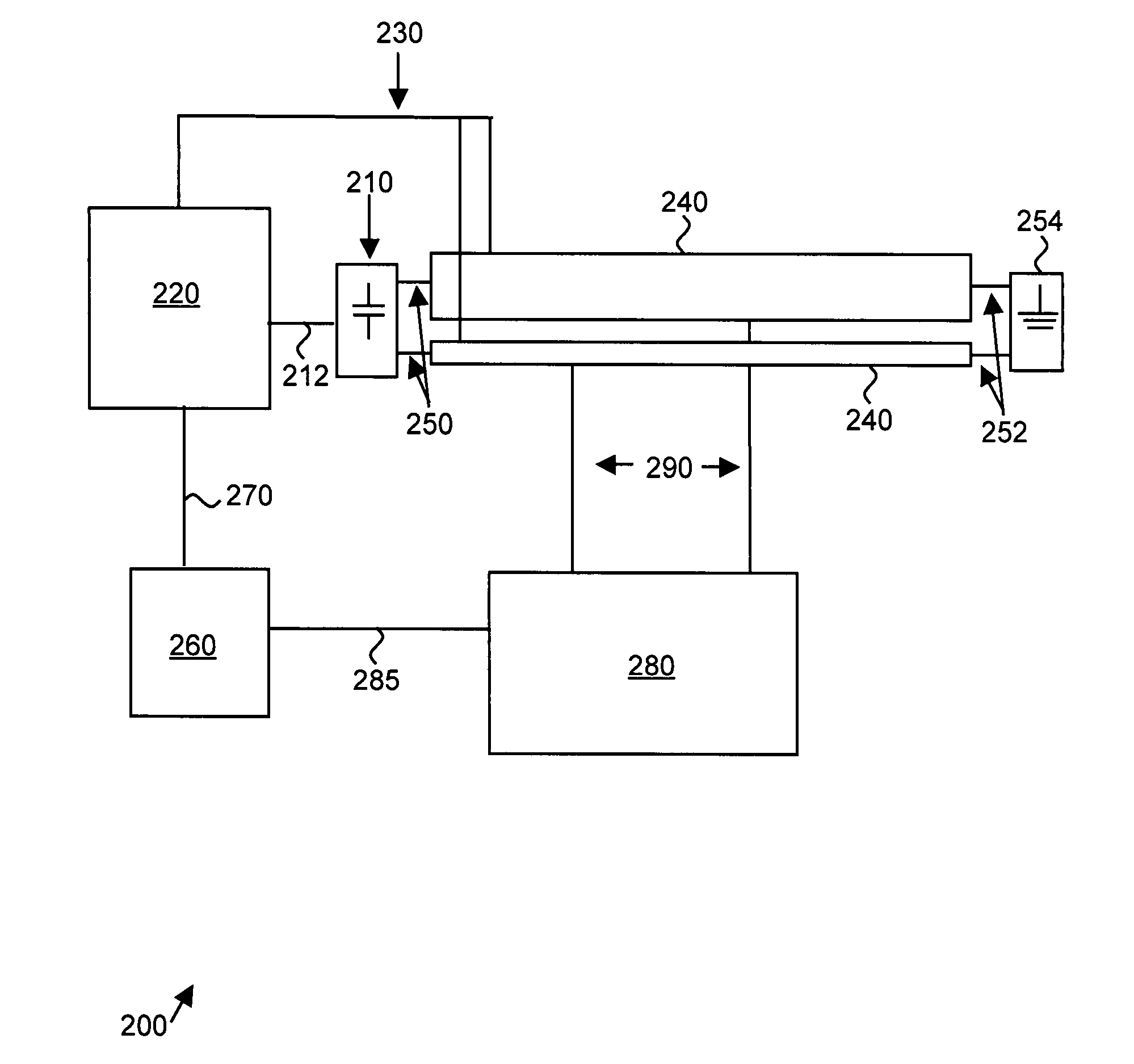
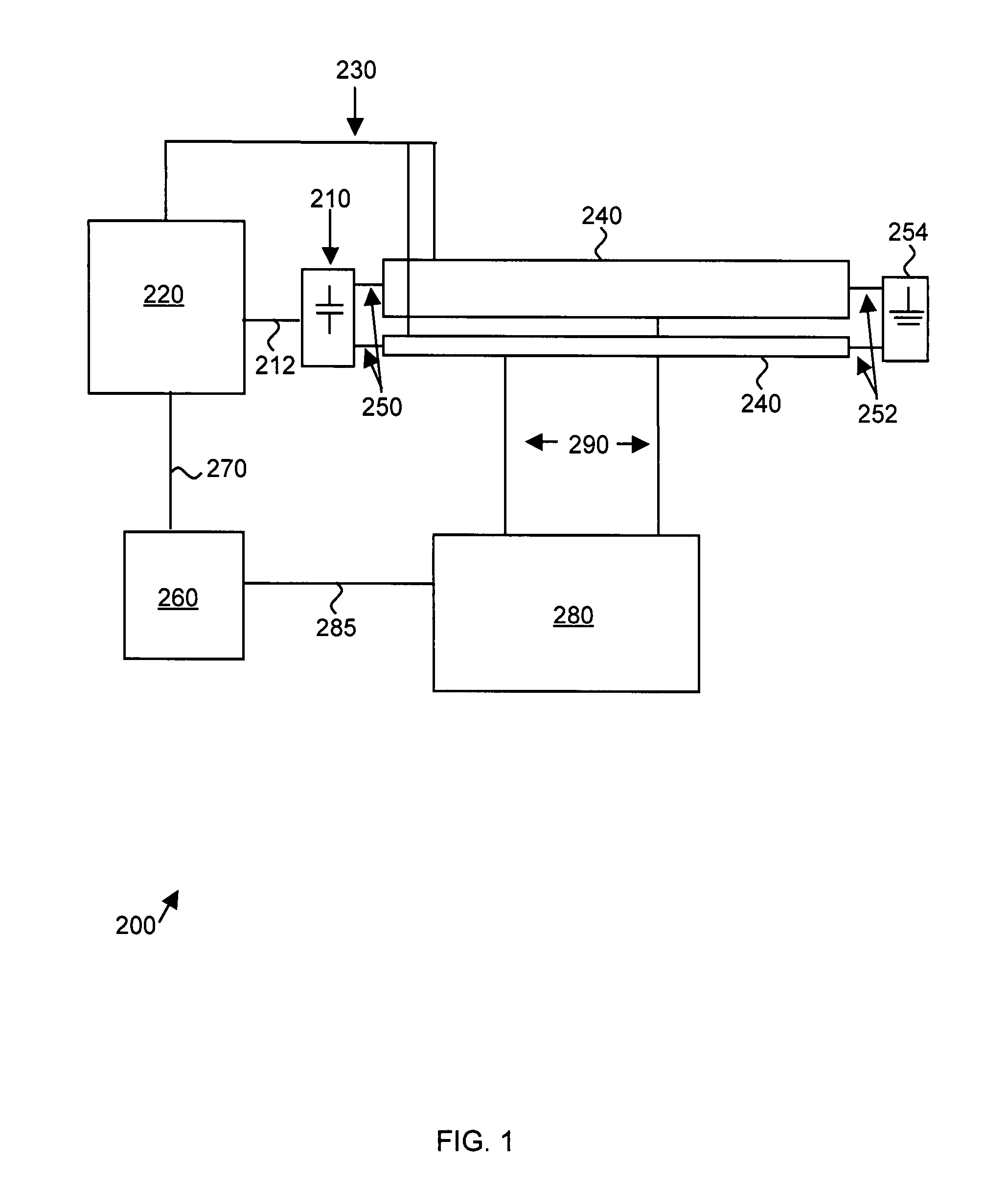
[0021] In the present invention, an improved circuit to charge the external capacitor was developed. Instead of a simple circuit, where the capacitor charging occurs through a high value resistor between transmissions, a smart charging circuit, coined the “Stepped Current Switch”, was created, which is driven by a measured battery voltage.

[0022] The Stepped Current Switch charges the capacitor using switched current sources. Preferably, at least four binary controlled current sources are used. At the initiation of charging, the highest current (8 mA) is automatically selected. During charging, if the battery voltage drops below a lower setpoint, e.g., 2.1 Volts, charging is halted by turning off all current sources. When the battery voltage recovers to greater than an upper setpoint, e.g., 2.6 Vo...


PUM


Abstract

The present invention provides a circuit and method for charging a capacitor with a power source. The circuit includes a capacitor, a power source, and at least two binary-controlled current sources. Each of these current sources is energized by the power source and provides either no current or a predetermined current to the capacitor. Importantly, the two predetermined currents are distinct. The circuit also includes a voltage comparator, which senses changes in the voltage of the power source. In addition, the circuit includes a logic device, which is electrically connected to the current sources and to the voltage comparator. The logic device selects one of the current sources to charge the capacitor based on information obtained by the voltage comparator, i.e. changes in voltage of the power source. Thus, this circuit allows a selectable charging current to be provided to the capacitor based on the voltage of the power source.

Description

CROSS-REFERENCE TO RELATED APPLICATIONS [0001] This application claims priority from U.S. Provisional Patent Application No. 60 / 832,312, filed Jul. 20, 2006, which is incorporated herein by reference.FIELD OF THE INVENTION [0002] The present invention relates generally to electronics. More particularly, the present invention relates to a circuit and method of charging a capacitor from a power source. BACKGROUND [0003] A battery increases its resistance as a function of the discharge (a discharged battery has higher internal resistance than a new one) and temperature (lower temperature increases internal resistance). In a tire pressure monitoring system (TPMS), the entire electronics operates from a single battery, which is expected to provide a 10 year life. [0004] Typically, the transmitter in a TPMS draws about 10 mA during transmission. Typically an open circuit battery voltage is 3 V, and a minimum operation voltage of the electronics is 2V. In such a case, a maximum allowed int...

Claims


Application Information

Patent Timeline
IPC IPC(8): H02J15/00
CPCH02J7/345
Inventor SCHILLER, CHRISTOPHER T.
Owner LV SENSOR
Why Eureka
Eureka Blog
Learn More