
Method and apparatus for forming hollow moldings having thin film on inner surface

a hollow molding and inner surface technology, applied in the direction of application, manufacturing tools, drawing profiling tools, etc., can solve the problems of high cost, failure of deposition, and high care of the substrate, and achieve the effects of improving molding efficiency, excellent deposited quality, and automatic formation with eas

Inactive Publication Date: 2008-04-03
JAPAN STEEL WORKS LTD
View PDF7 Cites 9 Cited by
  • Summary
  • Abstract
  • Description
  • Claims
  • Application Information

AI Technical Summary

Benefits of technology

[0010]The present invention contemplates to provide a molding method having solved the aforementioned problems of the related art, and has an object to provide a method for forming a hollow molding having a thin film on its inner surface, which has any deposited face contamination so that its quality is not deteriorated by the deposition failure, which does not need any special storage management, and which can be automatically molded with ease, and a molding apparatus to be used for practicing that molding method.
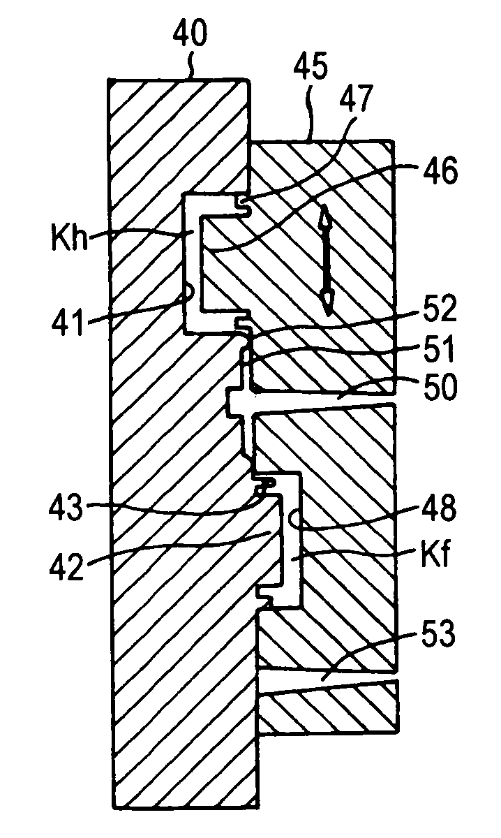
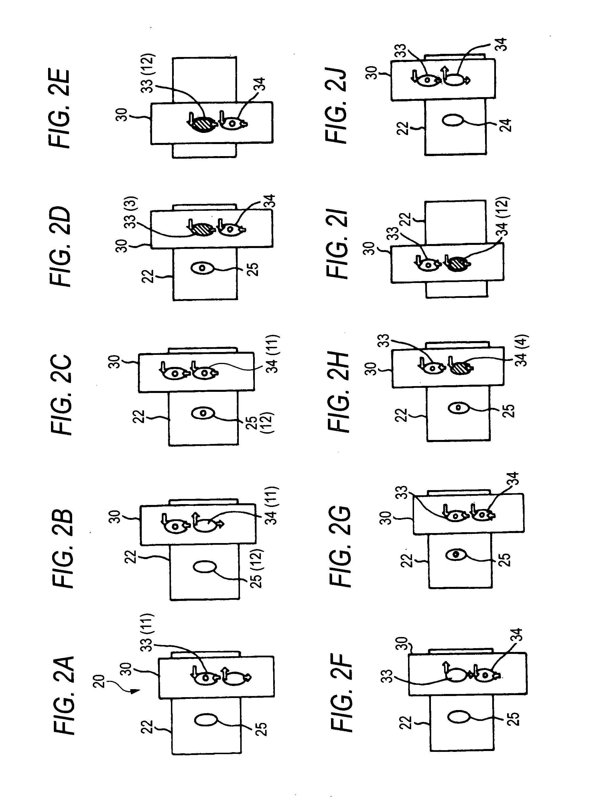
[0014]Thus, according to the invention, a pair of semi-hollow bodies are molded by using a stationary mold and a slidable movable mold, and the slidable movable mold is driven to a predetermined position while leaving the paired hollow bodies molded at the primary molding step, in their individual molds, to deposit the inner surface of at least one of the paired semi-hollow bodies while being covered with a depositing recess formed in the stationary mold and having a deposition element such as a target electrode, a substrate electrode or a vacuum suction pipe. In short, the paired semi-hollow bodies are not taken out from the mold but are deposited in the mold while being covered with the depositing recess, so that the deposited face is not soiled on its surface with hand or dust. It is, therefore, possible to provide a hollow molding of an excellent deposited quality having the thin film on its inner surface. Moreover, the deposition is performed in the mold while the semi-hollow bodies are left in the mold, so that the semi-hollow bodies need no storage management. According to the invention, moreover, the slidable movable mold is driven to the position, where the opening of the paired semi-hollow bodies registers, while the paired semi-hollow bodies, at least one of which is deposited, being left in the individual molds, thereby to mold clamp the slidable movable mold, so that the paired semi-hollow bodies are integrated by injecting a molten resin to their joint portions. By using the molds, even the hollow molding of a complicated shape having the thin film on its inner surface can be automatically formed with ease.
[0015]According to another invention, on the other hand, a plurality of pairs of semi-hollow bodies are molded by the primary molding step, and the inner surface of at least one of the paired semi-hollow bodies even pairing at the deposition step is deposited, and the paired semi-hollow bodies at the secondary molding step are integrated. In addition to the effects thus far described, the plurality of hollow moldings each having the thin film on its inner surface can be simultaneously produced to improve the molding efficiently.

Problems solved by technology

According to the forming methods described above, there arise many problems because the substrate has to be formed in advance by the injection molding method and has to be transferred into the vacuum tank for the deposition.
Therefore, the substrate may be soiled on its surface with hand or dust while being stored, so that it may cause a deposition failure.
In order to avoid this, the handling of the substrate requires the highest care and raises the cost.
Further, the prefabricated substrate is once stored so that its storage raises a management problem.
In addition, the substrate has to be once extracted from the mold before it is deposited, and has to be again inserted into the mold before it is jointed, thus lowering the productivity.
The molding methods of the related art, however, cannot form the thin film of the order of several microns on the inner surface of the hollow molding.

Method used


Image

  • Method and apparatus for forming hollow moldings having thin film on inner surface
  • Method and apparatus for forming hollow moldings having thin film on inner surface
  • Method and apparatus for forming hollow moldings having thin film on inner surface

Examples


Embodiment Construction

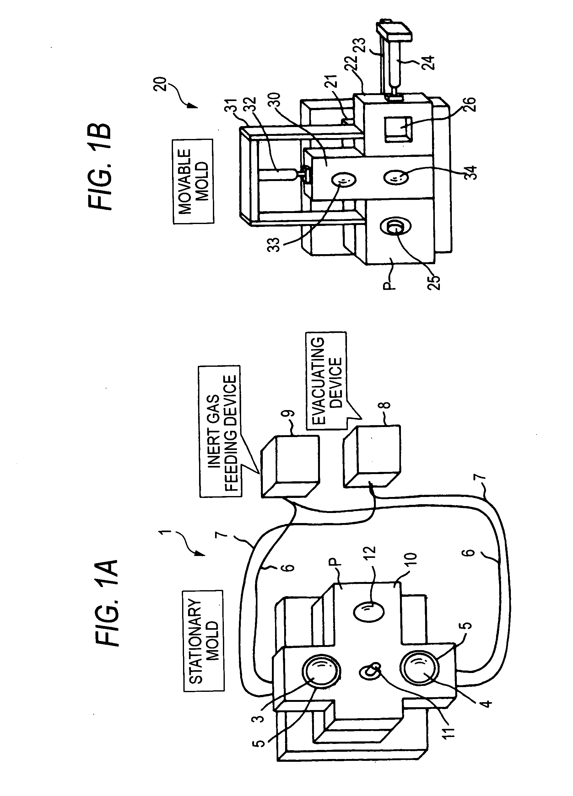
[0020]Here is described a molding example of a molding article having a thin film in its inside, which is formed by injection-molding a cup-shaped body portion and a plate-shaped cover member for sealing the opening of the body portion, by forming the thin film on the inner surface of the body portion in the mold, and by sealing the opening of the body portion with the cover member. An embodiment of a molding apparatus of the invention is described at first. FIG. 1 presents perspective views schematically showing the molding apparatus according to an embodiment of the invention. FIG. 1A is a perspective view of a stationary mold 1, as taken from a parting line side, and FIG. 1B is also a perspective view of a movable mold 20, as taken from the parting line side. In the shown embodiment, the stationary mold 1 has a parting line face P formed into a generally cross shape of a first vertically extending molding face 2 and a second horizontally extending molding face 10.

[0021]In the fir...


PUM

PropertyMeasurementUnit
negative voltageaaaaaaaaaa
pressureaaaaaaaaaa
shapesaaaaaaaaaa

Abstract

The method employs a stationary mold having depositing recesses equipped in its inside with a deposition element such as a target electrode, and movable molds made slidable. A primary molding is performed to form a body portion and a cover member to have joint portions around their opening. The body portion left in the vertically sliding mold is deposited after it was densely covered with the depositing recesses. Next, the deposited body portion and the cover member, as left in the molds, are registered and mold clamped, and the molten metal is injected to integrated the joint portions.

Description

[0001]This application is based on Japanese Patent Application No. 2005-153273, which is incorporated herein by reference.BACKGROUND OF THE INVENTION[0002]1. Field of the Invention[0003]The present invention relates to a method for forming a hollow molding integrated by jointing openings of a pair of semi-hollow bodies and having a thin film deposited on the inner surface of at least one semi-hollow body, and a molding apparatus to be employed for executing the molding method.[0004]2. Description of the Related Art[0005]A molding having a thin film of several micron orders partially on the inner surface of a hollow body is exemplified by a front lamp or a tail lamp, which is attached to a vehicle. This lamp is composed of a recessed body portion having an electric bulb, and a lens unit integrally attached to the opening of the body portion. The body portion is molded by an injection molding method, for example, and is suspended in a deposition-dedicated vacuum tank by means of a ded...

Claims


Application Information

Patent Timeline
Patent Type & Authority Applications(United States)
IPC IPC(8): B29C45/16B29C48/76
CPCB29C45/0062B29C2045/0067B29C2045/0063B29C66/54
Inventor NISHIDA, SHOSO
Owner JAPAN STEEL WORKS LTD
Learn More