
Hybrid vehicle

Active Publication Date: 2008-03-27
HONDA MOTOR CO LTD
View PDF24 Cites 78 Cited by
  • Summary
  • Abstract
  • Description
  • Claims
  • Application Information

AI Technical Summary

Benefits of technology

[0022]With this configuration of the hybrid vehicle, since the first input gear and the second input gear are meshed with one idle gear, the number of idle gears can be decreased when compared with the conventional hybrid vehicles. This enables the transmission mechanism for the first transmission passage and the second transmission passage to be small and light-weighted, thereby increasing design freedom upon arrangement of the components. Further, the reduction gear ratio for the first transmission passage and the reduction gear ratio for the second transmission passage can be set separately, so that the displacement of the engine and the capacity of the driving motor can be optimized based on an effective engine speed for the maximum driving force required for the engine or an effective motor speed for the maximum driving force required for the driving motor. The displacement of the engine and the capacity of the driving motor can be selected to achieve improved fuel consumption efficiency of the hybrid vehicle.
[0042]Furthermore, the output characteristic variable mechanism is allowed to combine, for example, valve opening and closing control, ignition timing control, and fuel injection control, other than the cylinder deactivation drive. As a result, the hybrid vehicle realizes more improved fuel consumption efficiency.

Problems solved by technology

However, the transmission efficiency of the driving force becomes relatively low in the series drive mode, and hence the fuel consumption of the vehicle may decrease accordingly.
When the vehicle runs in the steady drive mode, it is not possible to select an arbitrary engine speed range for achieving improved fuel economy, and hence the fuel consumption of the vehicle decreases as a result.
Especially in the combination of the engine driving force and the motor driving force of a hybrid vehicle equipped with a large displacement engine, an excessive driving force is large.
Further, even if an output characteristic variable mechanism such as variable cylinder management is combined with a large displacement multi-cylinder engine so as to achieve improved fuel economy, the setting of this lowered gear ratio is insufficient to achieve advantages of the output characteristic variable mechanism for controlling cylinder deactivation drive for improved fuel economy.
As a result of this, it is difficult to adapt this arrangement to a compact vehicle.
This results in an increased size of the entire transmission mechanism, increased weight, decreased fuel consumption efficiency, increased cost, etc.
Moreover, as the size of the transmission mechanism increases, the mounting space for the generator and the driving motor is limited so that the power generation capacity of the generator and the driving force of the driving motor are limited accordingly.
As a result, it may be difficult to realize a layout design which allows a transmission mechanism for hybrid vehicles to be also mounted in a space within the engine room of an existing non-hybrid vehicle.
When compared with other transmission mechanisms 101, 102, 103, 104 as shown in FIGS. 11A, 11B, 12A, and 12B, the transmission mechanism 105 requires one more gear transmission than the other transmission mechanisms, which leads to deteriorated transmission efficiency and thus deteriorated fuel consumption efficiency.
Therefore, it is necessary to change the engine rotation direction between a hybrid vehicle and a non-hybrid vehicle, which leads to an increase in manufacturing cost of the hybrid vehicle.

Method used


Image

  • Hybrid vehicle
  • Hybrid vehicle
  • Hybrid vehicle

Examples


first embodiment

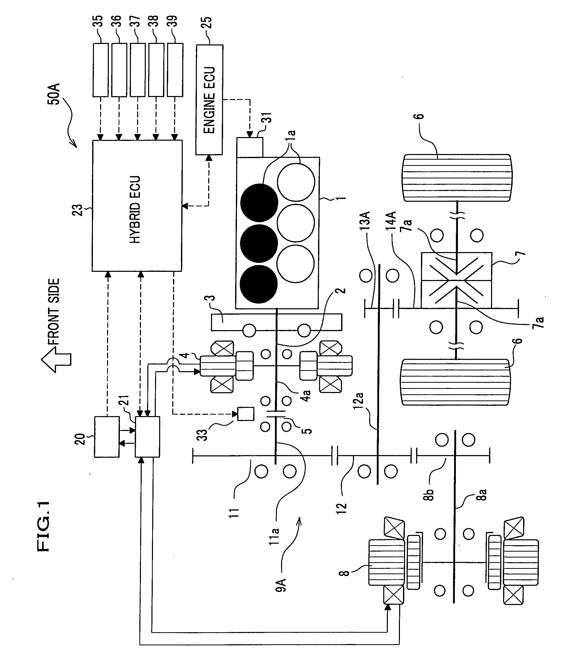
[0061]With reference to FIGS. 1 to 7, a hybrid vehicle according a first embodiment of the present invention will be described.

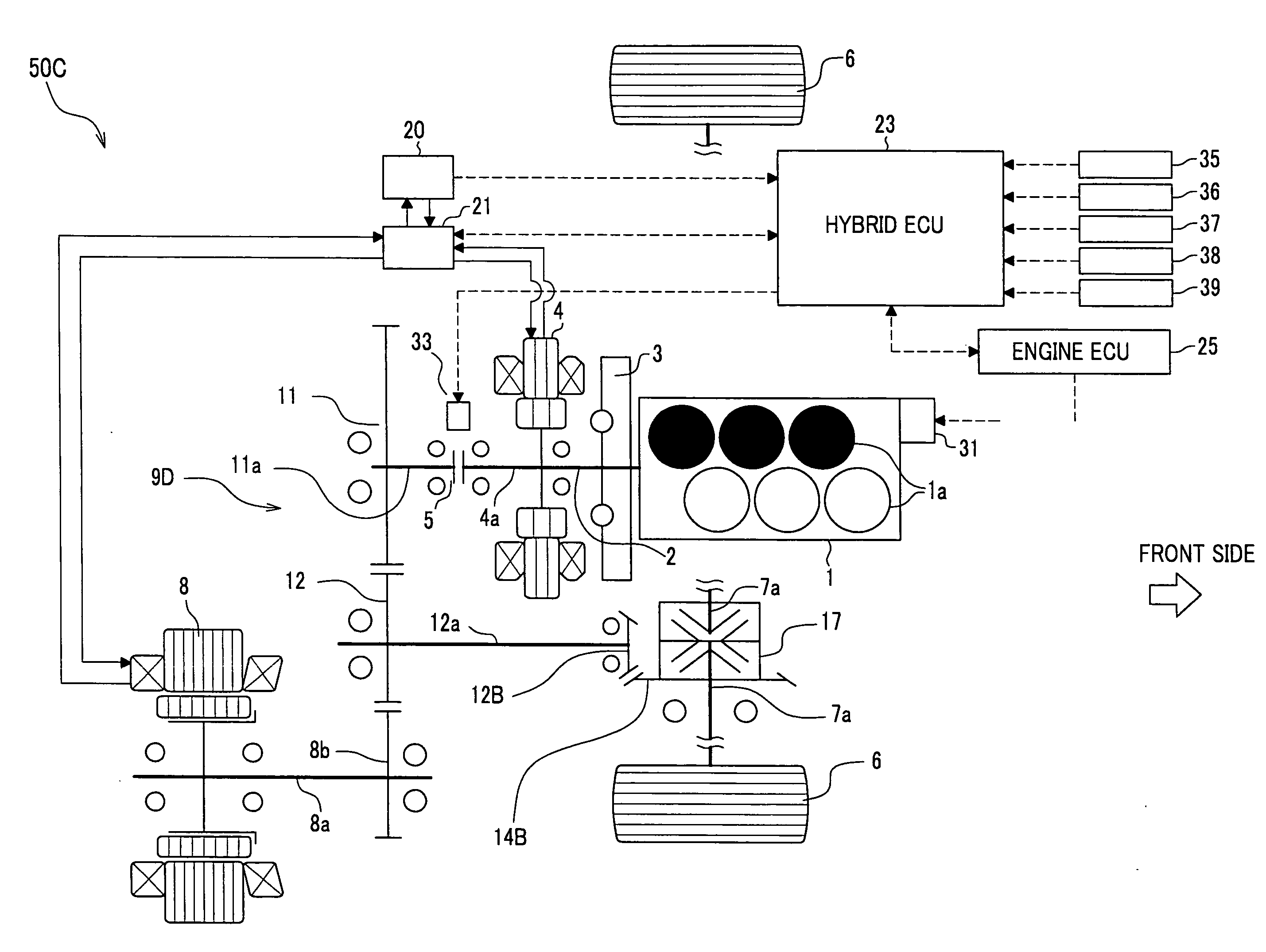
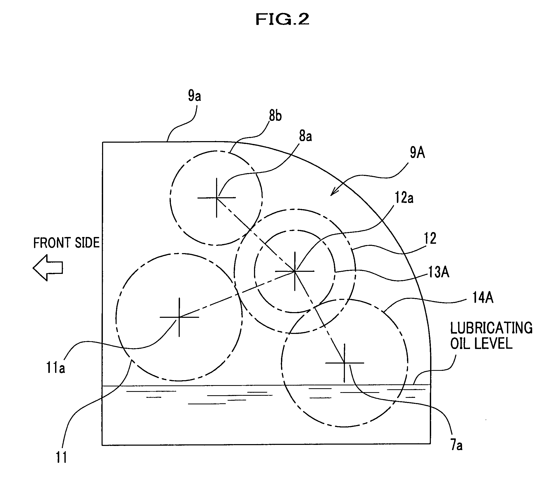
[0062]The overall arrangement of the hybrid vehicle 50A is schematically illustrated in FIG. 1, in which fixed gear type driving force transmission passages for an engine 1 and a driving motor 8 are provided. The transmission passages for transmitting engine driving force and motor driving force to driving wheels are provided by a transmission mechanism 9A. FIG. 2 shows an arrangement of gear shafts when viewing the transmission mechanism 9A from the left side of the vehicle. FIG. 3 is a graph showing driving force characteristics of the hybrid vehicle according to this embodiment, in which the horizontal axis indicates vehicle speed and the longitudinal axis indicates driving force or running resistance.

[0063]The hybrid vehicle 50A has a first transmission passage for transmitting driving force of the engine 1 to driving wheels 6, 6 to run the vehicle, and ...

second embodiment

[0115]With reference to FIG. 8, a hybrid vehicle 50B according to a second embodiment of the present invention will be described. The hybrid vehicle 50B is substantially the same as the hybrid vehicle 50A according to the first embodiment. However, in this hybrid vehicle 50B, a transmission mechanism 9C is configured such that the engine output gear 11, the idle gear 12, and the motor gear 8b are engaged with a single chain 15 to form a triangular loop and the driving force of the engine 1 and the driving force of the driving motor 8 are transmitted to the idle gear 12 via the chain 15. Parts similar to those previously described with reference to the first embodiment are denoted by the same reference numerals, and detailed description thereof will be omitted. As with the first embodiment, the chain 15 is housed in the transmission casing 9a, into which lubricating oil is charged for cooling and lubricating purposes.

[0116]In this hybrid vehicle 50B according to this second embodimen...


PUM


Abstract

A hybrid vehicle is provided with a first transmission passage for transmitting driving force of an engine to driving wheels and a second transmission passage for transmitting driving force of a driving motor to the driving wheels, and driven by selectively using or in combination of the first transmission passage and the second transmission passage. The hybrid vehicle includes: a first input gear for inputting the driving force of the engine; a second input gear for inputting the driving force of the driving motor; and an idle gear meshed with the first input gear and the second input gear, and transmitting at least one of the driving force of the engine and the driving force of the driving motor toward the driving wheels. The driving force to be input from at least one of the first input gear and the second input gear is transmitted to the driving wheels via the idle gear and the final differential gears.

Description

CROSS REFERENCE TO RELATED APPLICATIONS[0001]This application claims the foreign priority benefit under Title 35, United States Code, § 119(a)-(d) of Japanese Patent Application No. 2006-256272 filed on Sep. 21, 2006 in the Japan Patent Office, the disclosure of which is herein incorporated by reference in its entirety.BACKGROUND OF THE INVENTION[0002]The present invention relates to a hybrid vehicle which is driven by the combination of driving force of the engine (internal combustion engine) and driving force of the driving motor (electric motor), and more particularly to a hybrid vehicle having a first transmission passage for transmitting engine driving force to driving wheels and a second transmission passage for transmitting motor driving force to the driving wheels.[0003]For example, Japanese Patent No. 2942533 (see paragraphs [0015] to [0028]; FIGS. 1 and 2), which is also referred to as Patent Reference 1, discloses a known hybrid vehicle using driving force characteristics...

Claims


Application Information

Patent Timeline
IPC IPC(8): F16H37/06B60K6/20G06F17/00F02D7/00B60L50/16
CPCB60K1/02B60K6/405B60K6/442B60K6/485B60K6/547Y10T477/23B60T7/042F16H57/0421F16H57/0457Y02T10/6226Y02T10/6234B60T1/10Y02T10/62
Inventor KIDOKORO, TERUHISAHONDA, KENJIMORISHITA, NAOHISA
Owner HONDA MOTOR CO LTD
Learn More