Eureka AIR delivers breakthrough ideas for toughest innovation challenges, trusted by R&D personnel around the world.

Ventilation Control Based on Occupancy

a technology of ventilation control and occupancy, applied in ventilation systems, fire alarms, heating types, etc., can solve the problems of inseparable heated or chilled air from fresh air at the room level, limited schemes, and work equipment and/or work materials adding irritating or harmful chemicals to the air being respirated by the occupants, etc., to achieve more granular control in meeting

Active Publication Date: 2008-03-27
SIEMENS IND INC
View PDF15 Cites 78 Cited by
  • Summary
  • Abstract
  • Description
  • Claims
  • Application Information

AI Technical Summary

Benefits of technology

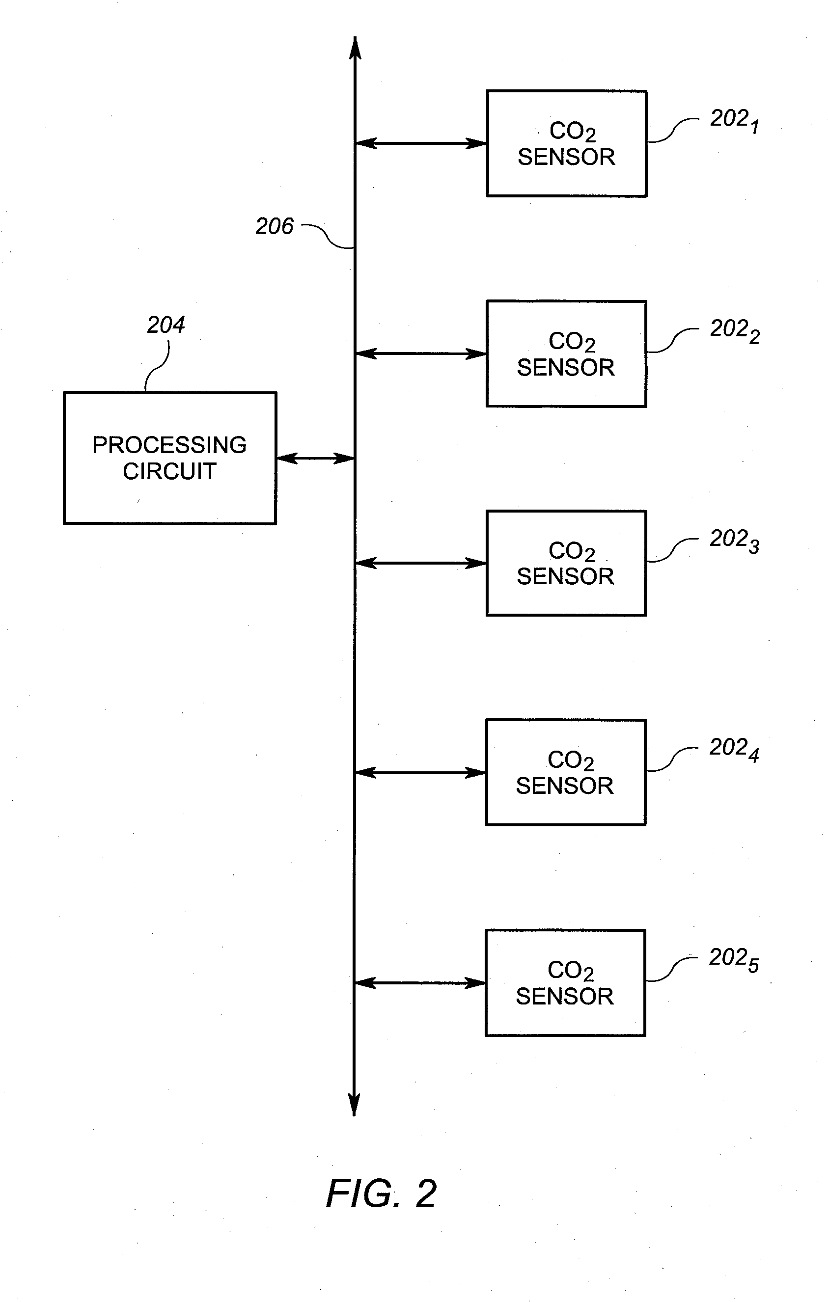
[0008]At least some embodiments of the present invention address the above-described need by providing a plurality of MEMS sensors that measure CO2 and controlling ventilation in the building based on CO2 value from the sensors. Other embodiments determine occupancy based on means other than CO2 sensing and control ventilation in the building based on the occupancy information. Some embodiments allow for ventilation (fresh) air and heating / cooling air to be provided to each space separately, allowing for more granular control in meeting the ventilation and temperature needs of each space.
[0010]In another embodiments, Microsystems may be used in other ways to obtain a measurement of occupancy or occupancy-based staleness within the facility. The amount of fresh air may be increased or decreased base on such measurements. In still other embodiments, fresh air may be separate supplied to rooms as a function of occupancy, thereby allowing for additional fresh air without significantly affecting temperature.

Problems solved by technology

In addition, work equipment and / or work materials can add irritating or harmful chemicals to the air being respirated by the occupants.
While the existing fresh air control schemes in HVAC systems provide some rough control of the fresh air in a building, these schemes are limited.
In particular, the existing systems only roughly correlate the need for fresh air with the control of fresh air.
Even if there were a way in which to more tightly control the amount of fresh air based on the measured need for fresh air, another drawback arises from the fact that the heated or chilled air is inseparable from the fresh air at the room level.
Conversely, if a particular room requires additional cooling, but does not require further ventilation, then fresh air is unnecessarily directed to spaces in which humans derive no benefit from the fresh air.

Method used


Image

  • Ventilation Control Based on Occupancy
  • Ventilation Control Based on Occupancy
  • Ventilation Control Based on Occupancy

Examples


Embodiment Construction

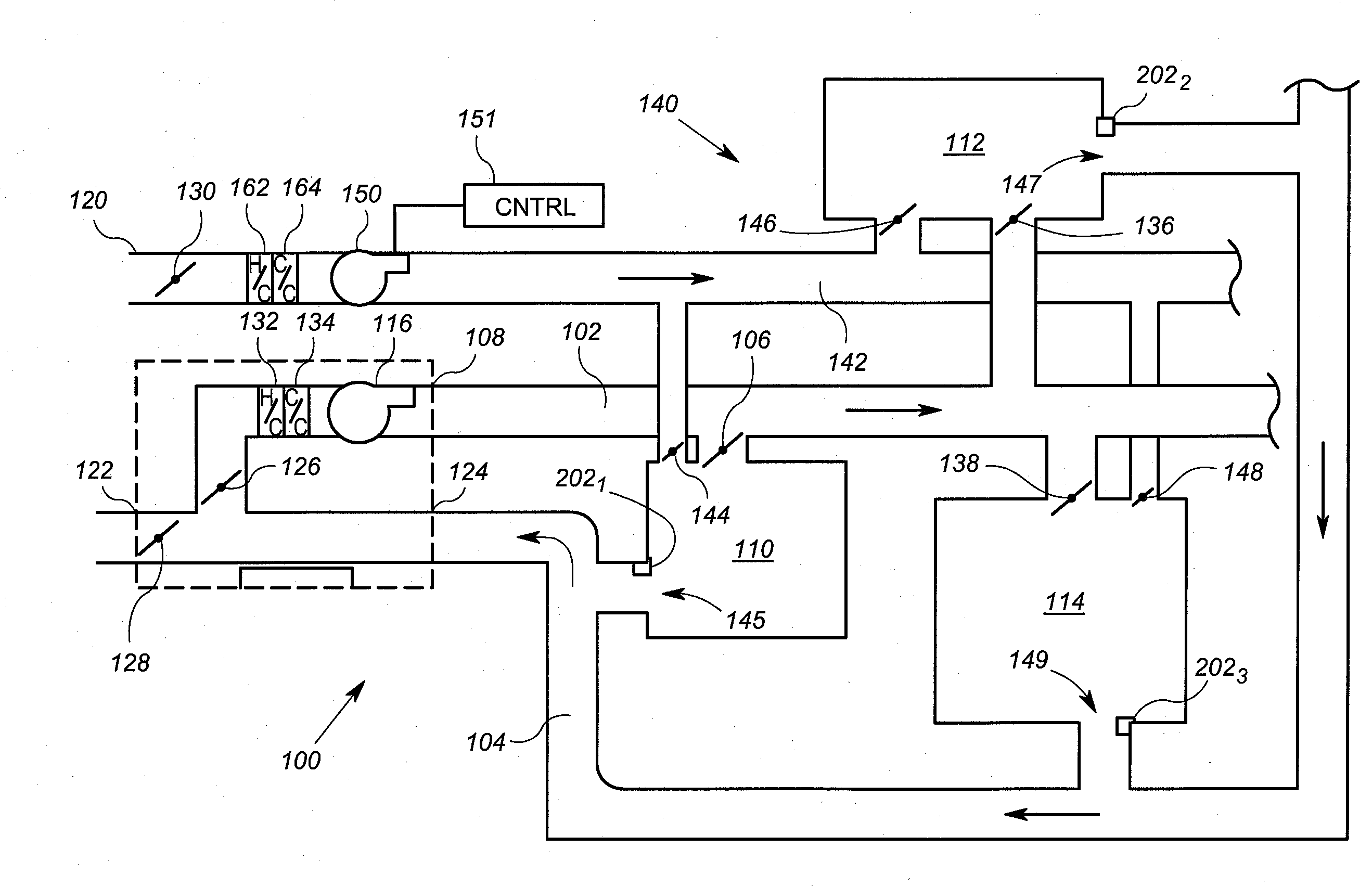
[0018]FIG. 1 shows an arrangement according to one embodiment of the invention that includes a portion of a exemplary HVAC system 100 and a portion of a fresh air ventilation system 140. Generally, the HVAC system 100 provides the heating and / or cooling to the building, while the ventilation system 140 provides fresh air to the building.

[0019]The portion of the HVAC system 100 illustrated in FIG. 1 includes a first (temperature-controlling air or “TCA”) supply duct 102, a first room TCA damper system 106, a second room TCA damper system 136, a third room TCA damper system 138, and an air handling unit 108. The HVAC system 100 provides heated, chilled and / or fresh air throughout a building having a multiplicity of zones, spaces and / or rooms. In general, the chilled air is used in warmer months of the year, and is chilled to a temperature that is below the lowest desirable air temperature within a building. Thus, the chilled air can be used to reduce temperature within a room or space...


PUM


Abstract

An arrangement for use in an occupancy-based ventilation system includes a plurality of CO2 sensors and a processing circuit. The plurality of CO2 sensors are disbursed throughout a plurality of spaces in a building. The processing circuit is operably coupled to receive information representative of CO2 measurements generated by the plurality of CO2 sensors. The processing circuit is operable to determine a value corresponding to occupancy, based on information from the CO2 sensors, and to control the flow of fresh supply air into the building ventilation system based on the determined value.

Description

[0001]This application claims the benefit of U.S. Provisional Patent Application Ser. No. 60 / 847,266, filed Sep. 26, 2006, which is incorporated herein by reference.FIELD OF THE INVENTION [0002]The present invention relates generally to building control systems, and more particularly, building control systems that control at least some aspects of ventilation throughout a building.BACKGROUND OF THE INVENTION [0003]Most building control systems or building automation systems operate to provide ventilation in the spaces of a building. Ventilation is important because living occupants within a building utilize the available oxygen in the ambient air over time through respiration. In addition, work equipment and / or work materials can add irritating or harmful chemicals to the air being respirated by the occupants.[0004]For many years, heating, ventilation and air conditioning (“HVAC”) systems have provided a mixture of fresh air into the chilled or heated supply air for the building. Thi...

Claims


Application Information

Patent Timeline
IPC IPC(8): F24F11/04G08B17/10
CPCF24F11/0017Y02B30/78F24F2011/0026F24F11/0034F24F11/30F24F2110/50F24F2110/70F24F2120/10Y02B30/70F24F11/77F24F11/63
Inventor AHMED, OSMAN
Owner SIEMENS IND INC
Why Eureka
Eureka Blog
Learn More