
Specimen sample rack

a sample rack and sample technology, applied in the field of specimen testing, can solve the problems of inefficient and inconvenient use of the devi

Active Publication Date: 2008-03-27
ABBOTT MOLECULAR INC
View PDF5 Cites 104 Cited by
  • Summary
  • Abstract
  • Description
  • Claims
  • Application Information

AI Technical Summary

Benefits of technology

[0013]In one aspect of the present invention, a rack for a plurality of capped tubes is provided. The rack has a frame having a longitudinally extending bottom base member having a row of spaced open top recesses, with each of the recesses adapted to receive one of the capped tubes. Vertical supports are at the ends of the row of recesses and fix a cover member above the base member. The cover member has openings therethrough smaller than the capped tubes. A wall is along one longitudinal side between the base member and the cover member, with...

Problems solved by technology

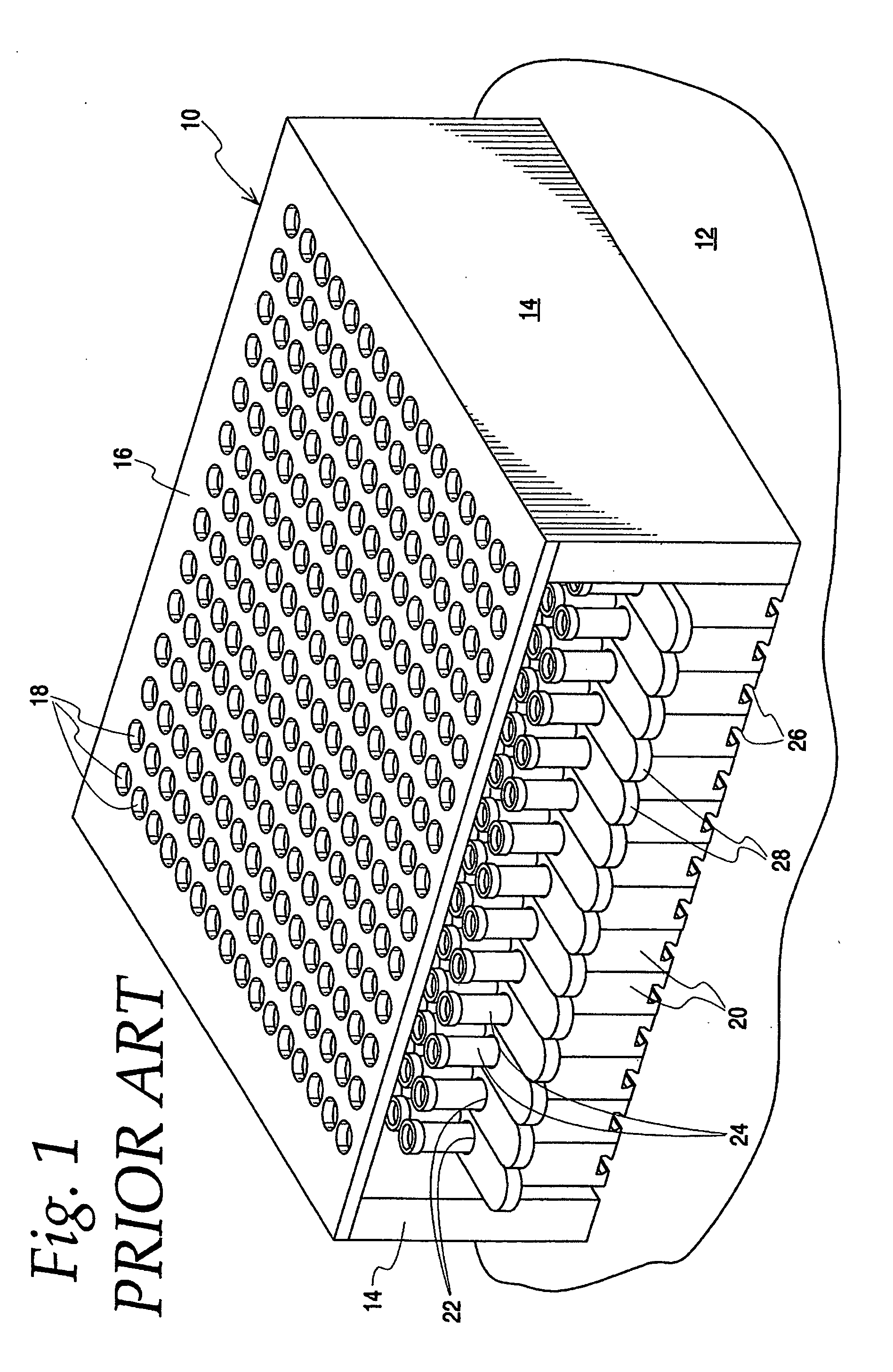
Thus, a pipette which is moved down through specific openings may not be aligned properly with the container 24 opening and could instead collide with and damage the container 24.
Further, it occupies the entire array on the device deck, and thus may either require that some tests be undesirably delayed (waiting on additional specimens requiring testing to fill up the rack before placing the rack on the device deck) or require inefficient use of the device (by mounting a rack occupying an entire array of container positions with only a few specimen containing containers).
Moreover, if it is desired to add or remove any container after the rack is mounted on the device deck, it is required that the cover member be removed and, during that time, pipettes may not be used to get specimens from any containers in the rack as none of the containers will be covered so as to prevent them from sticking on the pipettes and being undesirably carried from the rack when the pipettes retract.
Of course, securing the cover member over the rack, and removing the cover member from the rack, itself takes time which can result in inefficient use of the device which may have to sit idle waiting for that to be completed before starting the pipetting and / or container identification processes.

Method used


Image

  • Specimen sample rack
  • Specimen sample rack
  • Specimen sample rack

Examples


Embodiment Construction

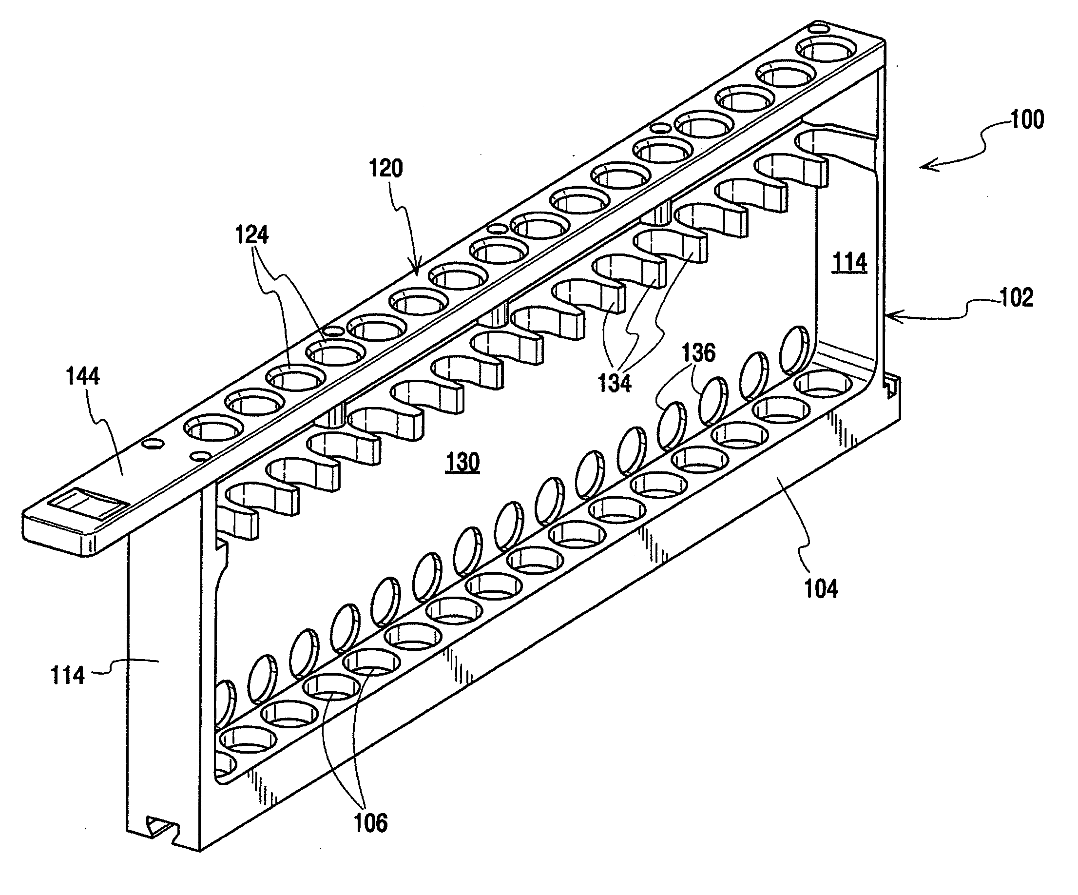
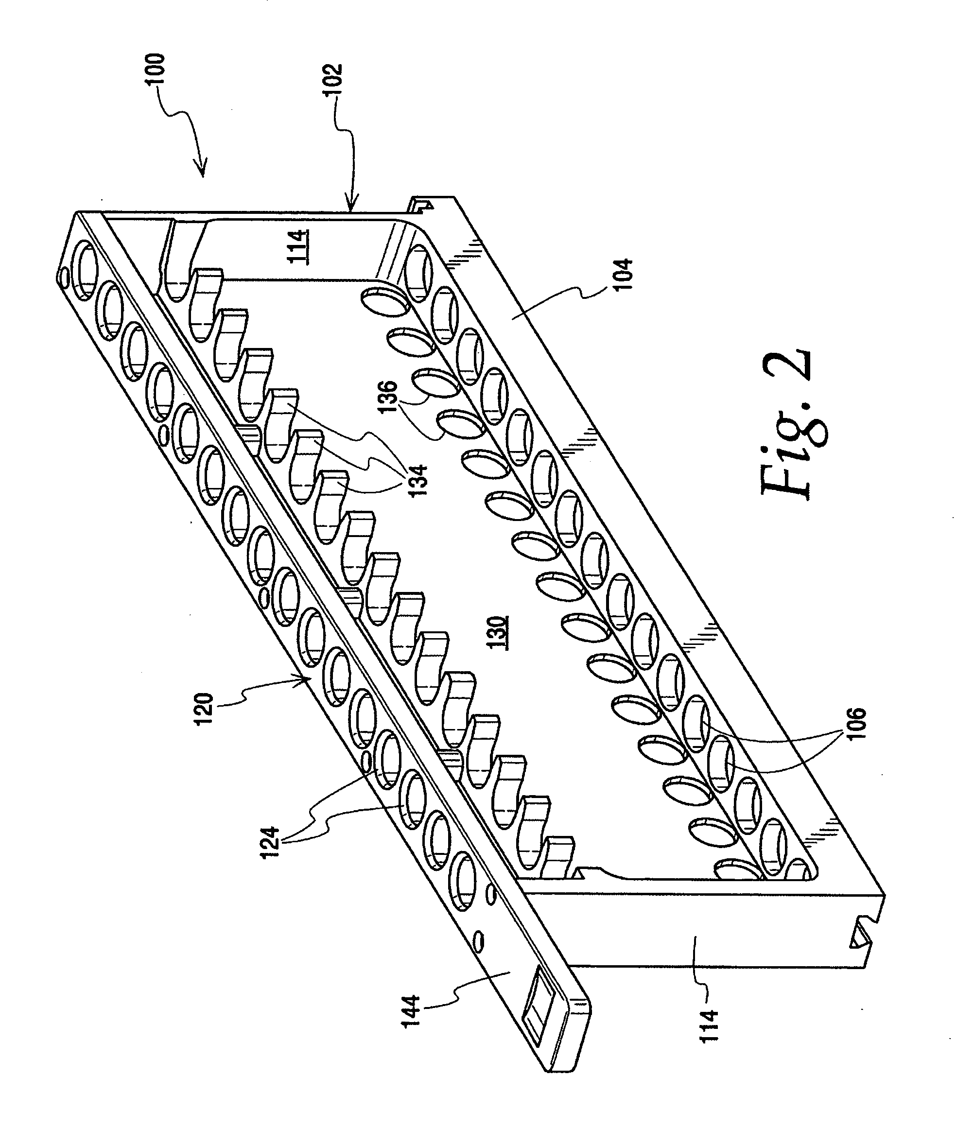
[0037]FIGS. 2-12 illustrate a specimen sample rack 100 in accordance with the present invention.

[0038]Specifically, the rack includes a frame 102 having a longitudinally extending bottom base member 104 which has a row of spaced open top recesses 106 adapted to receive capped containers or tubes 110 (see FIG. 12). Vertical supports 114 at the ends of the row of recesses 106 fix a top or cover member 120 above the base member 104. Intermediate supports 118 are also provided to ensure that the cover member is maintained in its supported position substantially parallel to the base member 104. It should be appreciated that the cover member 120 may be permanently fixed to the supports 114, 118 if desired, as normal operation as described below will not require removal of the cover.

[0039]The cover member 120 has openings 124 therethrough smaller than the capped tubes 110 so that the capped tubes 110 cannot fit through the openings 124.

[0040]A wall 130 is along one longitudinal side betwee...


PUM


Abstract

A rack for a plurality of capped tubes, including a frame having a longitudinally extending bottom base member having a row of spaced open top recesses adapted to receive the capped tubes. Vertical supports at the ends of the row of recesses fix a cover member above the base member. The cover member has openings therethrough smaller than the capped tubes. A wall is along one longitudinal side between the base member and the cover member, with the other longitudinal side between the base member and the cover member being open. Support fingers extend horizontally from the wall toward the open longitudinal side and are vertically aligned between the recesses to secure capped tubes in a generally vertical direction in a longitudinally extending vertical plane. The base member and cover member are vertically spaced a distance sufficient to permit tipped capped tubes to be moved into the frame with the tipped tubes then dropped into the recesses and tipped back to an upright vertical position.

Description

CROSS REFERENCE TO RELATED APPLICATION(S)[0001]Not applicable.STATEMENT REGARDING FEDERALLY SPONSORED RESEARCH OR DEVELOPMENT[0002]Not applicable.REFERENCE TO A MICROFICHE APPENDIX[0003]Not applicable.TECHNICAL FIELD[0004]The present invention relates to specimen testing, and more particularly toward a rack for supporting specimen containers in an automated specimen testing device.BACKGROUND OF THE INVENTION AND TECHNICAL PROBLEMS POSED BY THE PRIOR ART[0005]Automated specimen testing devices are widely used, for example, to test biological samples such as blood for medical purposes. In many such devices, efficient and cost effective testing requires that multiple specimen containers (e.g., test tubes) often be handled together for individual testing of the various specimens in the various containers.[0006]In such automated devices, a plurality of containers are often placed in an array on an input deck. In some devices, the containers are themselves transported from the input deck ...

Claims


Application Information

Patent Timeline
IPC IPC(8): B01L9/00
CPCB01L3/50855Y10S435/809B01L9/06
Inventor HERCHENBACH, STEPHEN L.PAVLOVIC, KIM E.
Owner ABBOTT MOLECULAR INC
Learn More