
Mobile Communication System, Wireless Line Control Station, Mobile Station, And Wireless Base Station

a mobile communication system and wireless line control technology, applied in the field of mobile communication systems, can solve the problems of large deterioration in the quality of uplink signals, increase in the load on the radio link in the opposite direction, and large influence on the mobile communication system caused by the load on the radio link in the opposite direction, and achieve the effect of improving the radio capacity

Inactive Publication Date: 2008-03-27
NTT DOCOMO INC
View PDF20 Cites 25 Cited by
  • Summary
  • Abstract
  • Description
  • Claims
  • Application Information

AI Technical Summary

Benefits of technology

The present invention aims to improve the radio capacity when retransmitting data blocks in a mobile communication system. The technical effects of the invention include reducing the number of retransmissions of transmission data blocks, improving the soft combining of retransmitted data blocks, and optimizing the use of network resources. These improvements can lead to better overall performance of the mobile communication system.

Problems solved by technology

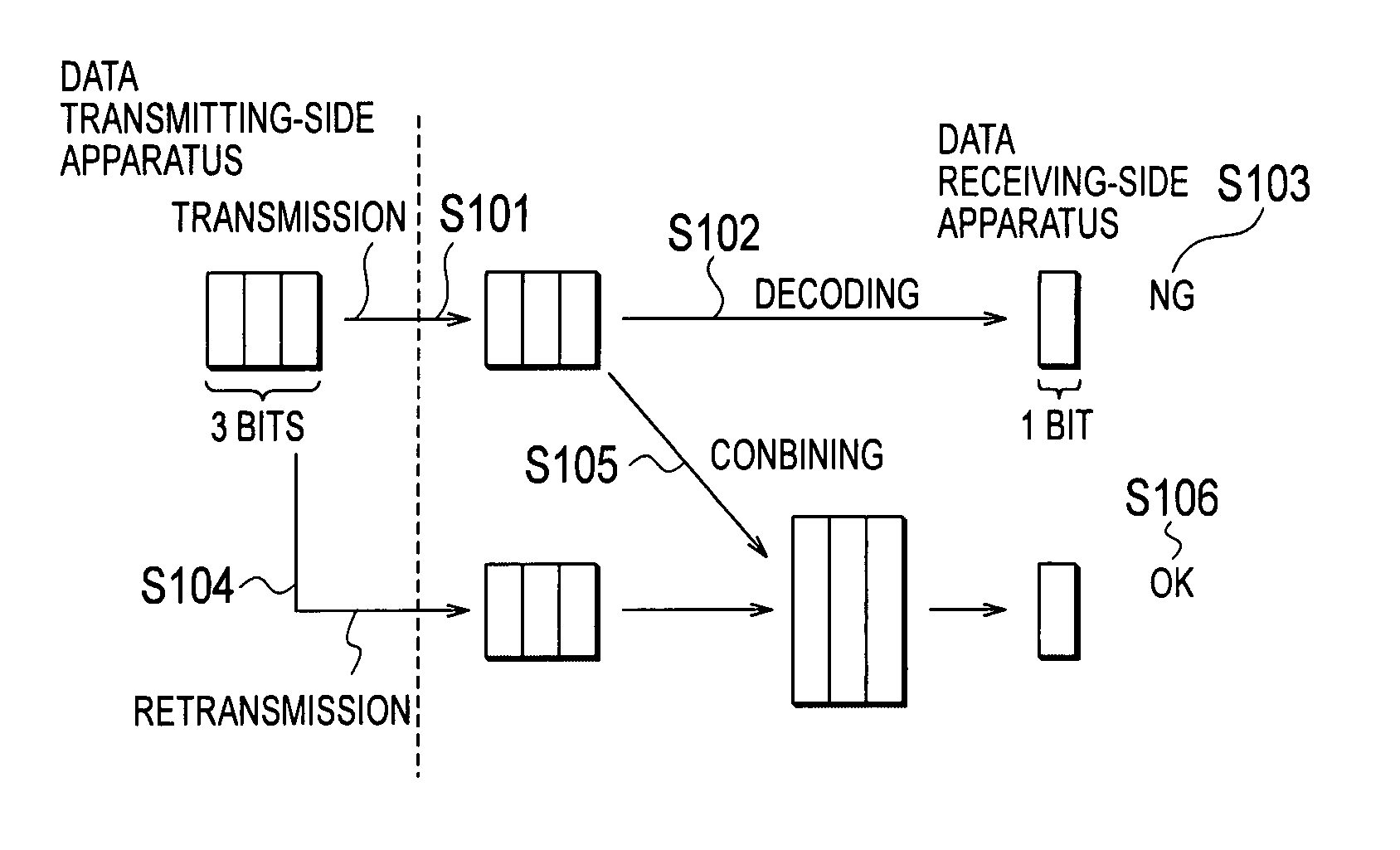
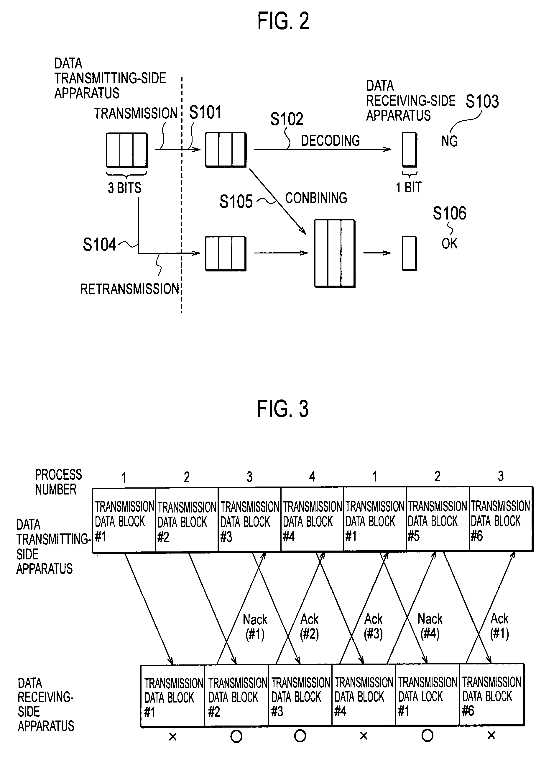
In a conventional mobile communication system, there is a problem of an increase of reception errors that results from large deterioration in the quality of uplink signals received by a radio base station and the quality of downlink signals received by a mobile station, because a received signal level in a data receiving-side apparatus instantaneously varies due to multi-path fading and the like.
However, it has a disadvantage that a transmission acknowledgement signal (Ack or Nack) is transmitted over a radio link in the opposite direction (a downlink is used when transmitting the transmission data block over an uplink, and the uplink is used when transmitting the transmission data block over the downlink), which results in an increase in load on the radio link in the opposite direction.
However, when the congestion degree of the radio link in the opposite direction is large, there is a problem that the influence on the mobile communication system caused by the load on the radio link in the opposite direction becomes large.

Method used


Image

  • Mobile Communication System, Wireless Line Control Station, Mobile Station, And Wireless Base Station
  • Mobile Communication System, Wireless Line Control Station, Mobile Station, And Wireless Base Station
  • Mobile Communication System, Wireless Line Control Station, Mobile Station, And Wireless Base Station

Examples


Embodiment Construction

(Configuration of Mobile Communication System According to the First Embodiment of the Present Invention)

[0049] Descriptions will be given of the configuration of the mobile communication system according to the first embodiment of the present invention with reference to FIGS. 4 to 13. As shown in FIG. 4, the mobile communication system of this embodiment includes a plurality of mobile stations UE#1 to #8, a plurality of radio base stations Node B#1 to #5, and a radio network controller RNC.

[0050] In the mobile communication system according to this embodiment, a data transmitting-side apparatus (a mobile station UE or a radio base station Node B) is configured to retransmit a transmission data block by using a data channel and a control channel, in response to a transmission acknowledgement signal (Ack or Nack) transmitted from a data receiving-side apparatus (a radio base station Node B or a mobile station UE).

[0051] Furthermore, the mobile communication system according to th...


PUM


Abstract

In a mobile communication system according to the present invention, based on a transmission acknowledgement signal transmitted from a data receiving-side apparatus, a data transmitting-side apparatus is configured to retransmit a transmission data block by using a data channel and a control channel, and the data receiving-side apparatus is configured to apply a soft combining to the retransmitted transmission data block. The data transmitting-side apparatus is configured in such a way that the number of retransmissions of the transmission data block can be set to 0.

Description

TECHNICAL FIELD [0001] The present invention relates to a mobile communication system, in which, based on a transmission acknowledgement signal transmitted from a data receiving-side apparatus, a data transmitting-side apparatus is configured to retransmit a transmission data block by using a data channel and a control channel, and in which the data receiving-side apparatus is configured to apply a soft combining to the retransmitted transmission data block; and to a radio network controller, a mobile station and a radio base station that are used in such mobile communication system. BACKGROUND ART [0002] In a conventional mobile communication system, there is a problem of an increase of reception errors that results from large deterioration in the quality of uplink signals received by a radio base station and the quality of downlink signals received by a mobile station, because a received signal level in a data receiving-side apparatus instantaneously varies due to multi-path fadin...

Claims


Application Information

Patent Timeline
Patent Type & Authority Applications(United States)
IPC IPC(8): H04Q7/00H04L1/18H04W28/04
CPCH04L1/1607H04L1/1803H04L1/1812H04W28/04H04L1/1845H04L1/1887H04L1/1822H04L1/18
Inventor USUDA, MASAFUMIUMESH, ANILNAKAMURA, TAKEHIRO
Owner NTT DOCOMO INC
Learn More