
Multi-phase Closed Loop LC Tank Circuits

a closed loop, circuit technology, applied in oscillator generators, generating/distributing signals, semiconductor devices, etc., can solve the problems of clock network and clock generation in vlsi chips, and achieve low power dissipation levels, high frequency behavior, and high performance circuit operation.

Inactive Publication Date: 2008-03-27
INTELLECTUAL VENTURES FUND 70
View PDF34 Cites 17 Cited by
  • Summary
  • Abstract
  • Description
  • Claims
  • Application Information

AI Technical Summary

Benefits of technology

The solution achieves a significant reduction in power dissipation by over two orders of magnitude and ensures synchronized clock signal distribution across the VLSI chip, addressing the challenges of high-frequency operation and large capacitance loads.

Problems solved by technology

Clock networks and clock generation in VLSI chips is a critical issue to high performance circuit operation.

Method used


Image

  • Multi-phase Closed Loop LC Tank Circuits
  • Multi-phase Closed Loop LC Tank Circuits
  • Multi-phase Closed Loop LC Tank Circuits

Examples


Embodiment Construction

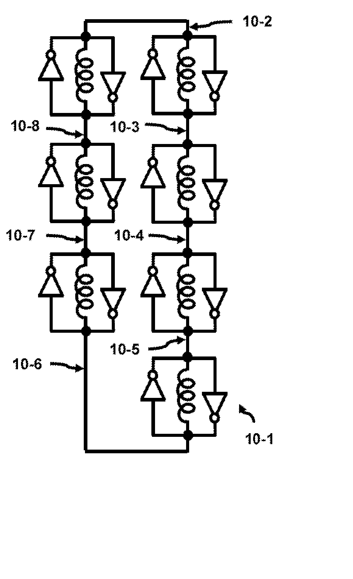
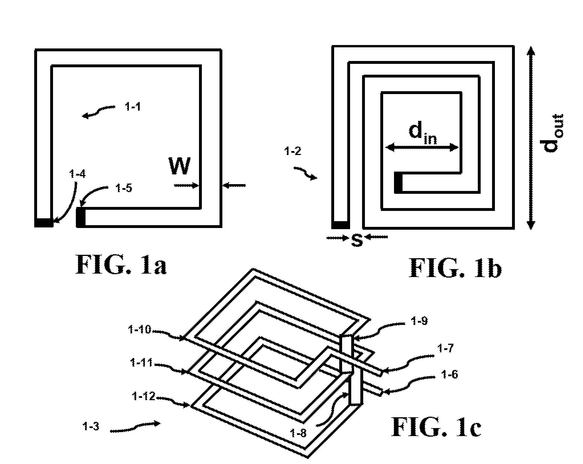
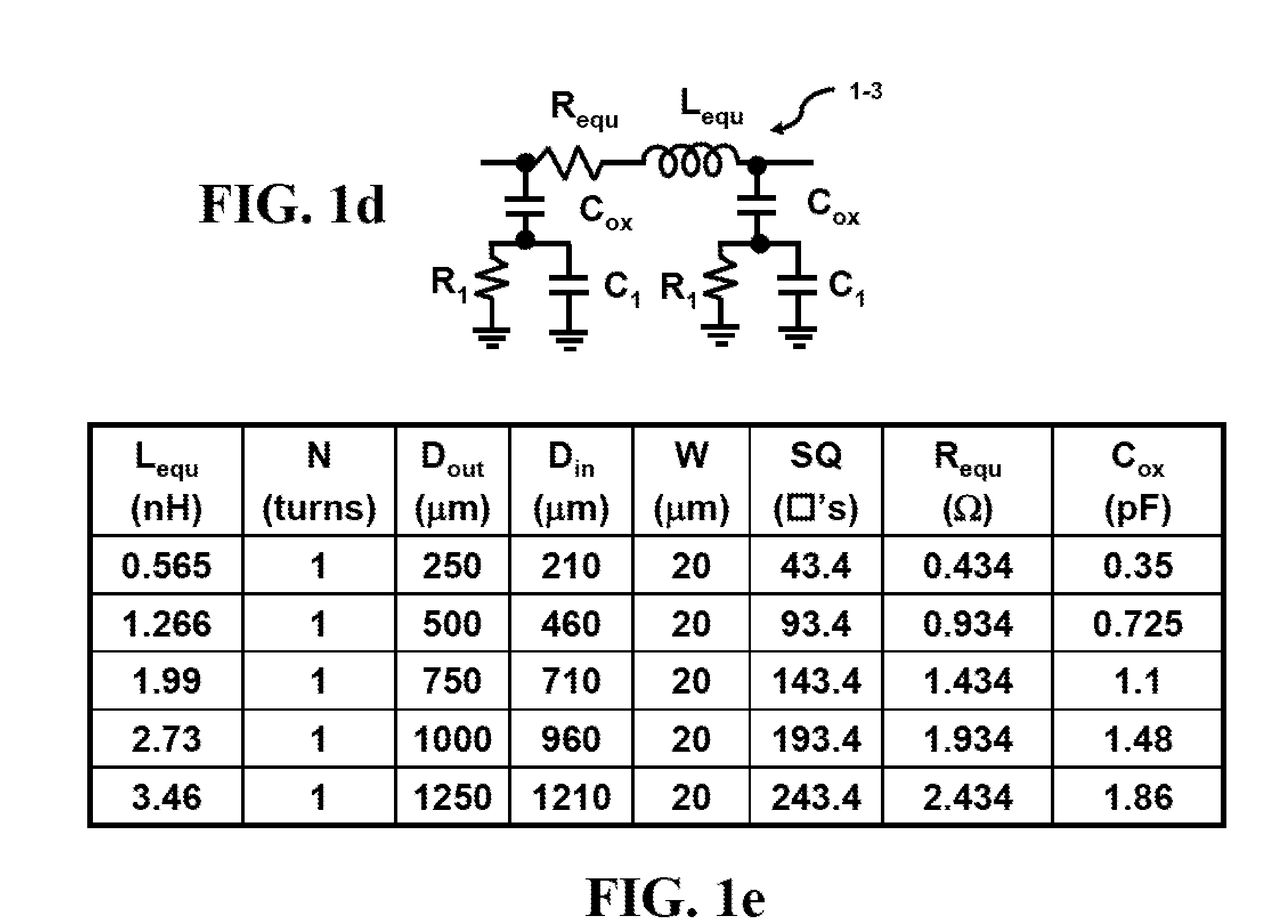
[0111] The LC (inductor-capacitor) tank circuit has been a fundamental building block in many electrical system designs. This circuit is used in wireless, digital, and mixed-signal designs. The basic building elements of the LC tank circuit consist of at least one inductor and and at least one capacitor.

[0112] The invention is based on the discovery that the flux linkage between inductors can be used to synchronize an interwoven network formed from individual LC tank circuits. The flux linkage that occurs between two inductors forms the basis of a structural unit known as a transformer. The coupling coefficient of the transformer can be utilized to lock an interwoven network of tank circuits so they operate in-phase. The ability to phase and frequency lock the interwoven network of tank circuits over the face of the die allows the generation of a unified clock waveform. The additional benefit is that the adiabatic nature of entire interwoven network reduces the power distribution o...


PUM


Abstract

LC tank circuits can be coupled together to form closed loop oscillators. The interconnectivity of these LC tank circuits were performed by a physical connection such as a metal interconnect. The LC tank circuits may also comprise a plurality of inductors that are coupled together in parallel. These closed loop oscillators generate oscillations which have multi-phase components. Such circuits are useful for RF designs, clock generation for VLSI chips, adiabatic circuitry, analog circuitry, and high-speed digital circuitry.

Description

CROSS-REFERENCE TO RELATED APPLICATIONS [0001] The present application is related to the co-filed U.S. applications entitled “MUTUAL INDUCTANCE IN TRANSFORMER BASED TANK CIRCUITRY”, “FABRICATION OF INDUCTORS IN TRANSFORMER BASED TANK CIRCUITRY”, and “FREQUENCY ADJUSTMENT TECHNIQUES IN COUPLED LC TANK circuits” filed on Jul. 19, 2005, which are invented by the same inventor as the present application and incorporated herein by reference in their entireties.BACKGROUND OF THE INVENTION [0002] Electronic consumer products are pushing both the bounds of computation complexity and high clocking frequencies. The systems that are experiencing these problems include: VLSI (Very Large Scale Integration), microprocessors, ASIC's (Application Specific Integrated Circuit), SOC (System On a Chip) and FPGA's (Field Programmable Gate Arrays). All of these systems operate at clock frequencies that increase dramatically each year. This higher clock frequency coupled with the increased size of the die...

Claims


Application Information

Patent Timeline
Patent Type & Authority Applications(United States)
IPC IPC(8): H03B19/12
CPCG06F1/10H03B2200/0076H03B5/1243H03B5/1212H03B5/1228H01L2224/16145
Inventor GABARA, THADDEUS JOHN
Owner INTELLECTUAL VENTURES FUND 70
Learn More