Ion beam irradiating apparatus and method of adjusting uniformity of a beam

a technology of ion beam and uniformity, which is applied in the direction of printers, instruments, therapy, etc., can solve the problems of adverse effects on the angle of parallelization and divergence of ion beam (the whole ion beam), and the quality of ion beam, so as to improve the uniformity of beam current density distribution

Inactive Publication Date: 2008-03-27
NISSIN ION EQUIP CO LTD
View PDF1 Cites 11 Cited by
  • Summary
  • Abstract
  • Description
  • Claims
  • Application Information

AI Technical Summary

Benefits of technology

[0005] Embodiments of the present invention provide an apparatus and method which can improve uniformity of a beam current density distri...

Problems solved by technology

Hence, there arises a problem in that the parallelism and divergence angle of the ion beam (the whole ion beam) are adversely affected.
Namely, there is a proble...

Method used


Image

  • Ion beam irradiating apparatus and method of adjusting uniformity of a beam
  • Ion beam irradiating apparatus and method of adjusting uniformity of a beam
  • Ion beam irradiating apparatus and method of adjusting uniformity of a beam

Examples


Embodiment Construction

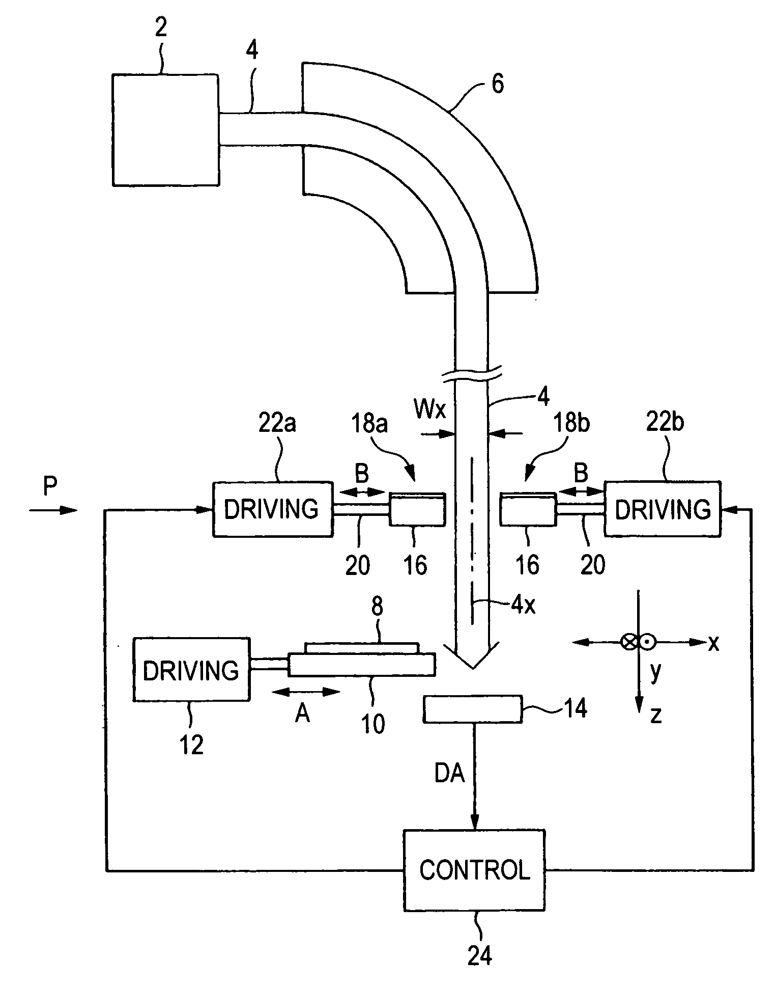
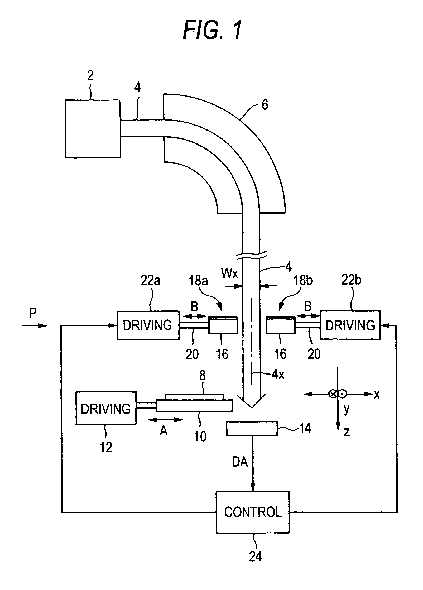
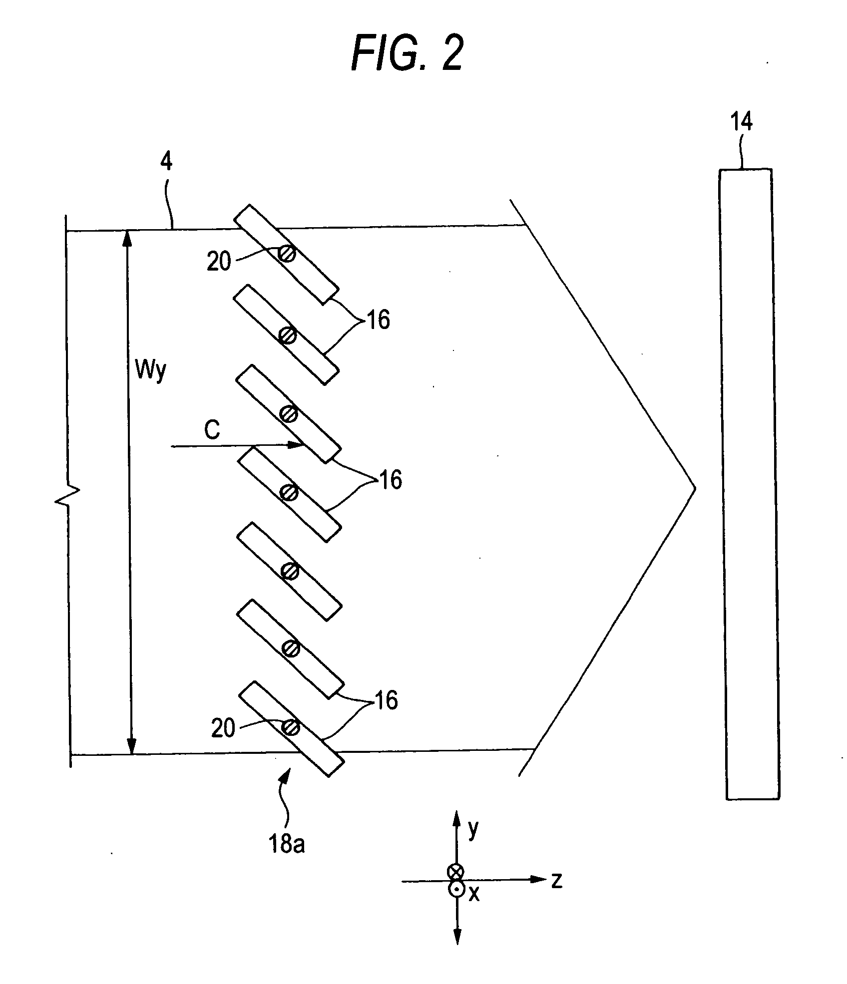
[0037]FIG. 1 is a plan view showing an embodiment of the ion beam irradiating apparatus of the invention, and FIG. 2 is a side view partly showing the periphery of movable shielding plates in FIG. 1, looking in the direction of the arrow P.

[0038] The ion beam irradiating apparatus is configured so that an ion beam 4 extracted from an ion source 2 passes through a mass separator 6 to be subjected to a mass separating process, is further accelerated or decelerated as required, and thereafter impinges on a target 8 held by a holder 10 to apply a process such as ion implantation on the target 8. The path of the ion beam 4 is maintained to a vacuum. In some cases, the mass separator 6 is not disposed. In the case where ion implantation is performed on the target 8, the apparatus is also called an ion implanting apparatus.

[0039] The ion beam 4 which is to be impinged on the target 8 has a shape in which the size Wy in y direction (the longitudinal direction, for example, vertical direct...


PUM


Abstract

An ion beam irradiating apparatus has: a beam profile monitor 14 which measures a beam current density distribution in y direction of an ion beam 4 in the vicinity of a target 8; movable shielding plate groups 18a, 18b respectively having plural movable shielding plates 16 which are arranged in the y direction so as to be opposed to each other across an ion beam path on an upstream side of the position of the target, the movable shielding plates being mutually independently movable in x direction; shielding-plate driving devices 22a, 22b which reciprocally drive the movable shielding plates 16 constituting the groups, in the x direction in a mutually independent manner; and a shielding-plate controlling device 24 which, on the basis of measurement information obtained by the monitor 14, controls the shielding-plate driving devices 22a, 22b to relatively increase an amount of blocking the ion beam 4 by the opposed movable shielding plates 16 which correspond to a position where a measured y-direction beam current density is relatively large, thereby uniformity of the beam current density distribution in the y direction.

Description

TECHNICAL FIELD [0001] The present disclosure relates to an ion beam irradiating apparatus which irradiates a target with an ion beam having a so-called ribbon-like (this may be also called a sheet-like or a strip-like, and the same will apply hereinafter) shape where the size in y direction (longitudinal direction) in a plane intersecting with the traveling direction is larger than that in x direction perpendicular to the y direction, thereby performing ion implantation or the like, and also to a method of adjusting uniformity of a beam which improves uniformity of the beam current density distribution in the y direction of the ion beam. In the specification, a ribbon-like ion beam includes an ion beam which has a ribbon-like shape without undergoing scanning in the y direction, and that which has a ribbon-like shape after undergoing scanning in the y direction. RELATED ART [0002] In the case where a target (for example, a semiconductor substrate, or a glass substrate) is irradiate...

Claims


Application Information

Patent Timeline
IPC IPC(8): H01J37/08
CPCH01J37/09H01J37/304H01J2237/0455H01J2237/0458H01J2237/31703H01J2237/2446H01J2237/24507H01J2237/24535H01J2237/30455H01J2237/24405H01J37/30H01J37/317H01L21/265
Inventor IKEJIRI, TADASHI
Owner NISSIN ION EQUIP CO LTD
Why Eureka
Try Eureka