
Rapid Release and Anti-Drip Porous Reservoirs

a porous reservoir, rapid release technology, applied in the direction of liquid handling, tobacco, separation processes, etc., can solve the problems of limiting the usefulness of prior art reservoirs, low dissolution rate, or low dissolution rate, etc., to achieve the effect of enhancing dissolution and transport volum

Inactive Publication Date: 2008-03-27
POREX TECHNOLOGIES CORP
View PDF10 Cites 2 Cited by
  • Summary
  • Abstract
  • Description
  • Claims
  • Application Information

AI Technical Summary

Benefits of technology

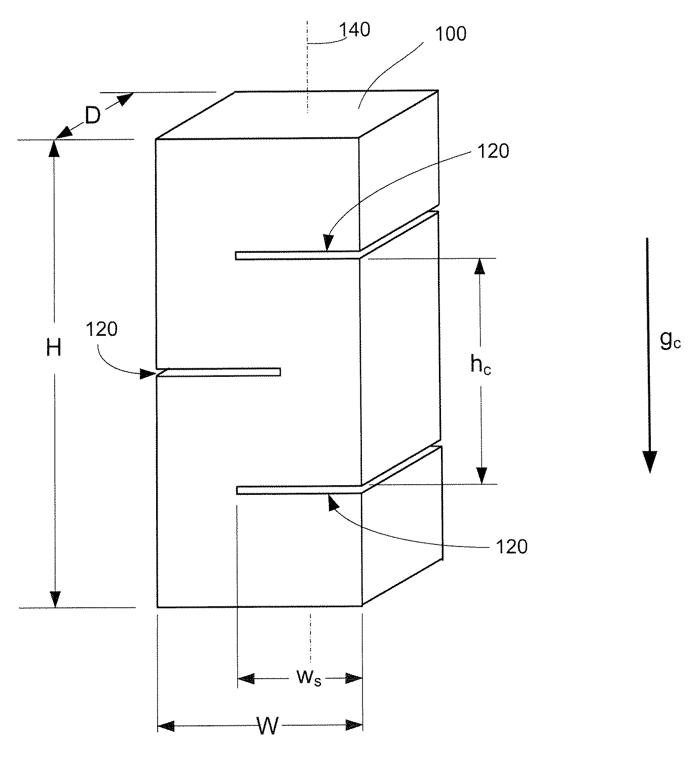
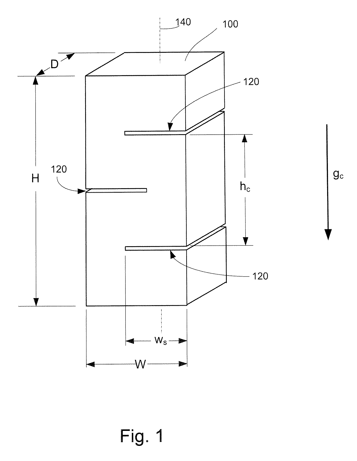
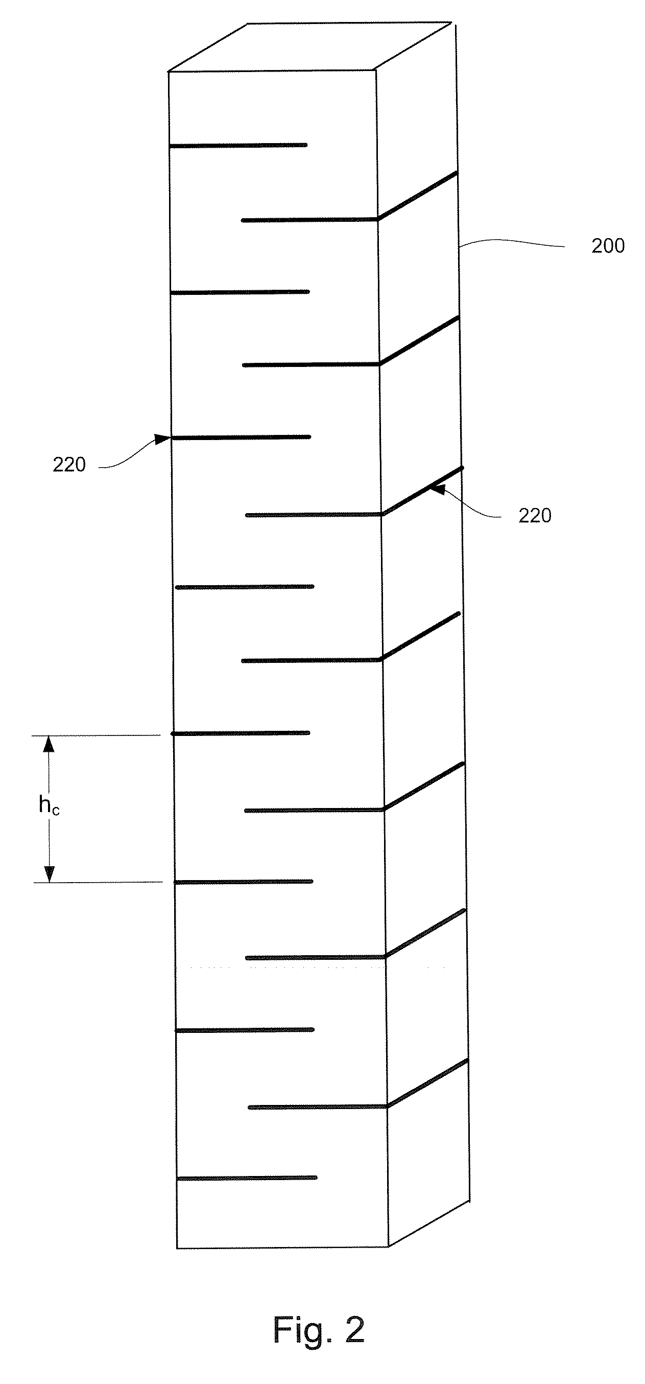
[0007] Another aspect of the invention provides a method of enhancing dissolution and transport volume of a three dimensional, porous reservoir. The three dimensional porous reservoir initially has a plurality of reservoir capillaries formed therein and an initial void volume, fluid-holding capacity, external surface area and effective capillarity in a predetermined direction. The effective capillarity is initially less than a length component in the predetermined direction of a first set of capillaries that is at least a majority of the reservoir capillaries. The method comprises forming at least one lateral indentation in a surface of the reservoir having a vertical surface component. The lateral indentation defines opposing reservoir surfaces, each having a lateral surface component orthogonal to the predetermined direction. The lateral indentation produces a net increase in a ratio of external surface area to volume for the reservoir.

Problems solved by technology

Unfortunately, porous reservoirs generally exhibit a tradeoff between the volume of material that can be held in the porous reservoir (referred to herein as the material “transport volume”) and the rate at which the loaded fluid or solid material may be removed from the reservoir and dispersed or dissolved into the miscible fluid (the “dissolution rate”).
In particular, reservoirs having a high transport volume generally have low dissolution rates.
Conversely, reservoirs with large areas of exposed surface so as to produce high dissolution rates generally have comparatively low transport volumes and or exhibit leakage problems.
These problems tend to limit the usefulness of prior art reservoirs in applications where high transport volume and high dissolution rates are desirable.

Method used


Image

  • Rapid Release and Anti-Drip Porous Reservoirs
  • Rapid Release and Anti-Drip Porous Reservoirs
  • Rapid Release and Anti-Drip Porous Reservoirs

Examples


example 1

[0046] A cylindrical bonded bicomponent polyolefin fiber reservoir structure with nominally 85% void volume, about 70 mm long and about 24 mm in diameter with a 4 mm diameter hole through its longitudinal center was made. The reservoir shape was formed in a die under length-oriented tension using steam as the heating medium, and then cut to length. The reservoir was elastic enough to recover completely from a 5% extension. The external diameter of the reservoir was sized to fit into the neck of a typical spray bottle. The diameter of the channel or hole of the reservoir was sized to accommodate the 4 mm o.d. dip tube of a typical household cleaner spray nozzle. The capillary strength of the reservoir was sufficient to hold about 17 grams of a cleaner concentrate solution. The reservoir included partial thickness slits (i.e., lateral indentations having essentially zero height) along the length of the reservoir alternating on each side with 5 mm spacing between slits. The slit depth ...

example 2

[0050] The reservoir of Example 1 was stretched beyond a yield point of the reservoir material, thereby extending the original length and causing the slits to open. The reservoir was stretched to twice its original length dimension, thereby producing wider slit openings. The elongated reservoir was mounted on a dip tube and placed in a spray bottle, following a process similar to that outlined in Example 1. The reservoir experienced improved concentrate release characteristics when compared to a comparable reservoir without slits. Throughout the test period, the slit / extended reservoir exhibited a dissolution rate more than twice that of an un-slit reservoir. The results for dissolution versus time were similar to the reservoir of Example 1.


PUM

PropertyMeasurementUnit
heightaaaaaaaaaa
slit heightaaaaaaaaaa
diameteraaaaaaaaaa

Abstract

A fluid reservoir for retaining a particular fluid against an environmental force is disclosed. The fluid reservoir includes a three dimensional porous body that has a plurality of reservoir capillaries formed therein and has a transport volume and effective capillarity in the force direction for the particular fluid when the porous body is oriented in a predetermined orientation. The fluid reservoir also includes at least one lateral indentation in a surface of the porous body. Each of the at least one lateral indentation defines opposing reservoir surfaces each having a lateral surface component orthogonal to the force direction. The at least one lateral indentation is configured so that at least a majority of the reservoir capillaries have a force-aligned length component that is less than the effective capillarity for the particular fluid.

Description

[0001] This application claims the benefit of U.S. Provisional Application No. 60 / 847,454, filed Sep. 27, 2006, which is incorporated herein by reference in its entirety.BACKGROUND OF THE INVENTION [0002] The invention relates generally to porous reservoirs, and, more particularly, to an improved porous reservoir with an enhanced ability to retain a relatively large volume of a fluid or solid and release the fluid or solid into another environment. Even more specifically, this invention relates to three dimensional, self-sustaining, porous reservoirs. [0003] Porous reservoirs formed from foam, cloth, non-woven fabrics, paper, sponges, bundled and / or bonded or unbonded natural or man-made fibers, porous metal or plastics, porous ceramic, cotton, linen, and similar fiber-based parts, pumice, asbestos, vermiculite, fused sand and fiber glass may absorb and / or hold various liquid or solid materials. In some applications, such “loaded materials” may be held in a porous article until the ...

Claims


Application Information

Patent Timeline
Patent Type & Authority Applications(United States)
IPC IPC(8): B65D85/804B29D22/00
CPCB01F13/002B01F13/0098Y10T428/1376B01F15/00512B01F15/00883B01F15/00506B01F33/35B01F33/5011B01F35/32021B01F35/3202B01F35/531
Inventor STOLTZ, GEOFFREY M.WARD, BENNETT C.BINSHTOK, RONALD J.LISK, JAMES R.
Owner POREX TECHNOLOGIES CORP
Learn More