
Procedure for the operation of an internal combustion engine

a technology for internal combustion engines and procedures, applied in the direction of machines/engines, electric control, instruments, etc., can solve the problems of difficult open-loop control of the combustion process and especially the open-loop control of the self-ignition, and achieve the effect of reducing the frequency

Inactive Publication Date: 2008-03-20
ROBERT BOSCH GMBH
View PDF3 Cites 19 Cited by
  • Summary
  • Abstract
  • Description
  • Claims
  • Application Information

AI Technical Summary

Benefits of technology

[0005] A task of the invention at hand is therefore to present a procedure, a device and a computer program, which avoid misfires, respectively self-ignition which is too early or too late during a charge cycle of the internal combustion engine, or at least reduce their frequency.
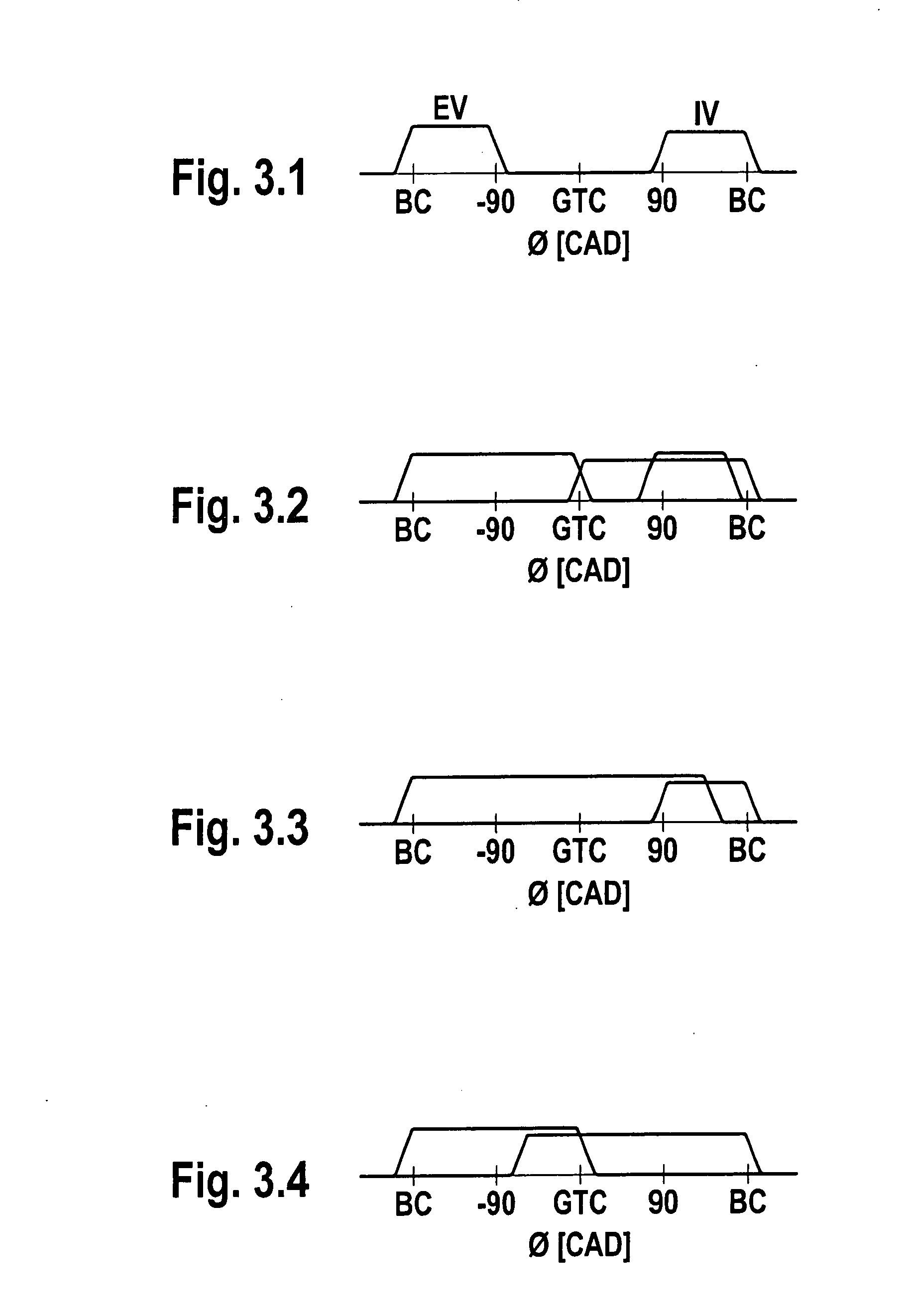
[0019] A quick map-based pilot control and closed-loop control of such a changeover without regard for the engine torque is advantageous. A combination of map-based pilot control and cycle-synchronous closed-loop control is used according to the invention. The invention allows for the changeover from the mode of operation with externally-supplied ignition to the mode of operation with self-ignition and back again. It is thereby assumed that a partially variable valve-train assembly is available (intake valve / exhaust valve phase setting and intake / exhaust valve lift changeover).

Problems solved by technology

The closed-loop control of the combustion process and especially the open-loop control of the self-ignition are, however, not simple.

Method used


Image

  • Procedure for the operation of an internal combustion engine
  • Procedure for the operation of an internal combustion engine
  • Procedure for the operation of an internal combustion engine

Examples


Embodiment Construction

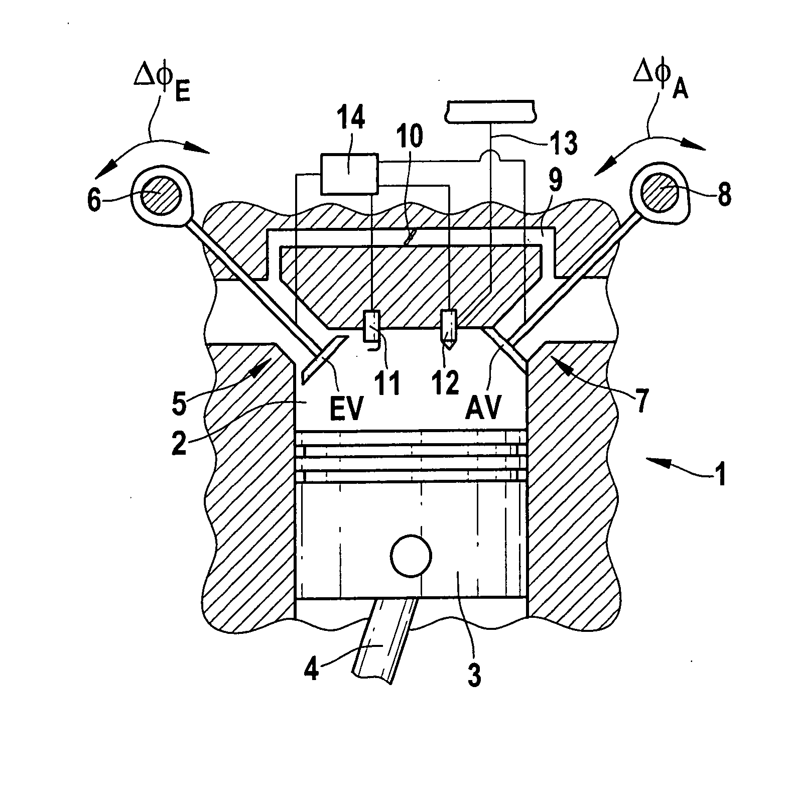
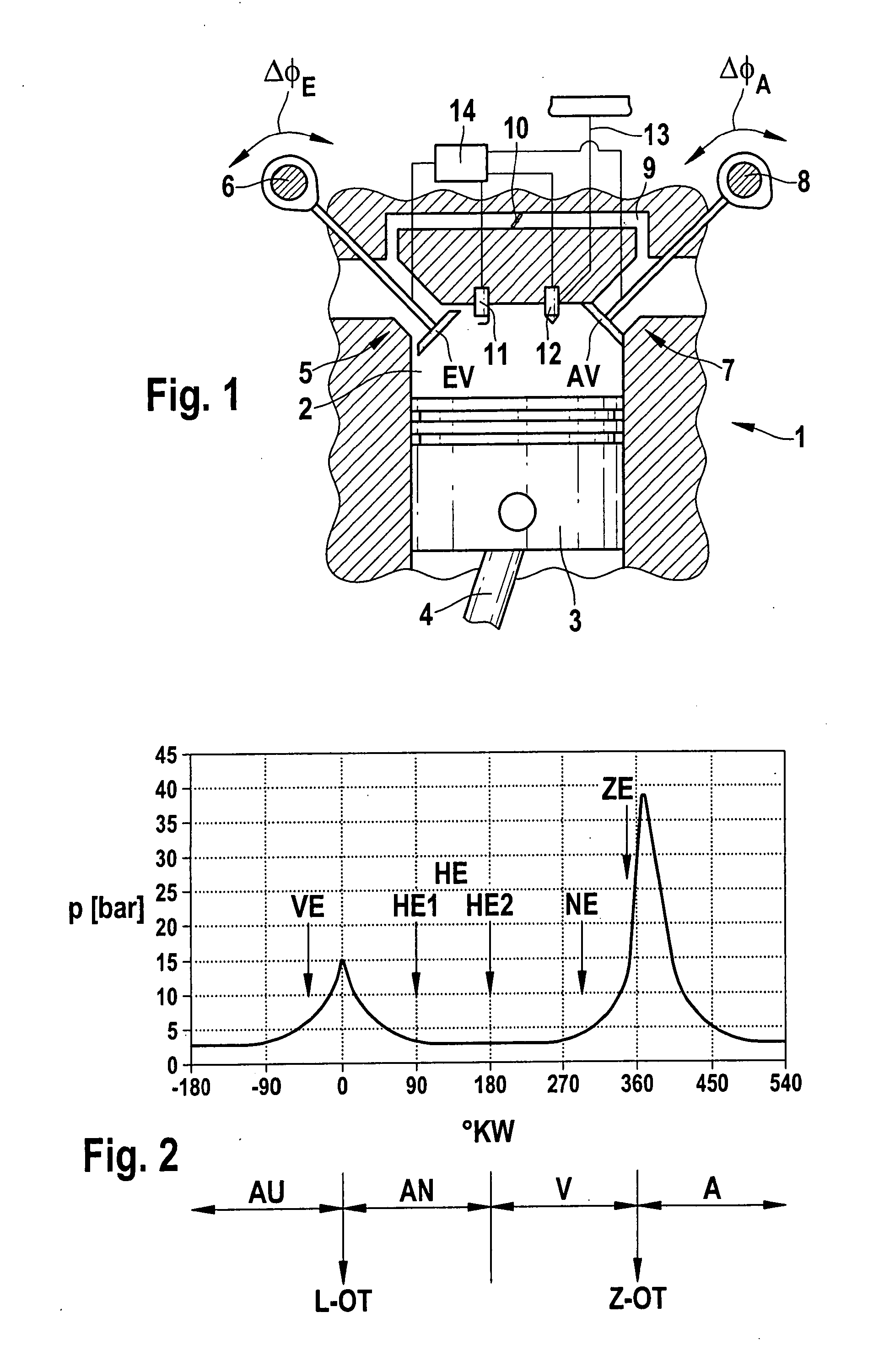
[0029] Using FIG. 1 the technological environment of the invention is first described. A cylinder 1 is depicted of an otherwise unspecified internal combustion engine, which as a rule consists of multiple cylinders. The cylinder 1 comprises a combustion chamber 2, in which a piston 3 with a connecting rod 4 is disposed in a manner capable of repositioning. The connecting rod 4 is connected to an unspecified crankshaft. An intake inlet 5 with an intake valve EV opens out into the combustion chamber 2. Additionally an exhaust outlet 7 with an exhaust valve AV opens out into the combustion chamber 2. The intake valve EV as well as the exhaust valve AV is actuated by way of an adjustable camshaft, or as depicted here with two adjustable camshafts 6, 8. The internal combustion engine is then equipped with a so-called partially variable valve control system. In the partially variable valve-train assembly like this one, which is known from the German patent DE 199 29 393, the valve timing ...


PUM


Abstract

Procedure for the transition of an internal combustion engine, particularly a gasoline engine with direct gasoline injection and with a partially variable valve-train assembly, from an initial mode of operation into a target mode of operation, whereby the initial mode of operation and the target mode of operation are either a mode of operation with an externally-supplied ignition or one with self-ignition. The procedure comprises the procedural steps: Adaptation of the operating parameters of the initial mode of operation to the required values for the target mode of operation in a map-based pilot control phase Changeover of the mode of operation after the map-based pilot control phase Closed-loop control of the operating parameters after the changeover.

Description

STATE OF THE ART [0001] The invention at hand concerns a procedure for the operation of an internal combustion engine, particularly a gasoline engine with direct gasoline injection and controlled self-ignition. The invention furthermore concerns a device as well as a computer program to implement the procedure. [0002] When operating an internal combustion engine in the HCCI mode (Homogenous Charge Compression Ignition), which sometimes is also denoted as CAI (Controlled Auto Ignition), ATAC (Active Thermo Atmosphere Combustion) or TS (Toyota Soken), the ignition of the air-fuel mixture does not result from an externally-supplied ignition but from a controlled self-ignition. The HCCI combustion process can, for example, be brought about by a large proportion of residual gases and / or by a high compression and / or a high temperature of the inflowing air. A precondition for self-ignition is a sufficiently high energy level in the cylinder. Internal combustion engines capable of being dri...

Claims


Application Information

Patent Timeline
IPC IPC(8): F02D28/00
CPCF02D35/027F02D41/307F02D41/3041F02D41/3035F02D41/3047F02D41/402Y02T10/40
Inventor CHRIST, ANSGARFISCHER, WOLFGANGCASAL KULZER, ANDRE F.
Owner ROBERT BOSCH GMBH
Learn More