
Network redundancy method and middle switch apparatus

a network redundancy and switch technology, applied in data switching networks, frequency-division multiplexes, instruments, etc., can solve the problems of lack of ports, insufficient number of ports of aggregation switches, and high cost of added chassis types of aggregation switches

Inactive Publication Date: 2008-03-20
FUJITSU LTD
View PDF5 Cites 61 Cited by
  • Summary
  • Abstract
  • Description
  • Claims
  • Application Information

AI Technical Summary

Benefits of technology

[0014]The present invention is contrived in view of the above-mentioned problem, and an object of the present invention is to provide a network redundancy method and a middle switch by which the box type switch can be used as a middle switch that is added for increasing the number of ports of the upper switch apparatus, redundancy function is realized, and it is not necessary to change settings of existing apparatuses.
[0024]According to the present invention, the box type switch can be used as a middle switch that is added for increasing the number of ports of the upper switch apparatus, redundancy function is realized, and it is not necessary to change settings of existing apparatuses.

Problems solved by technology

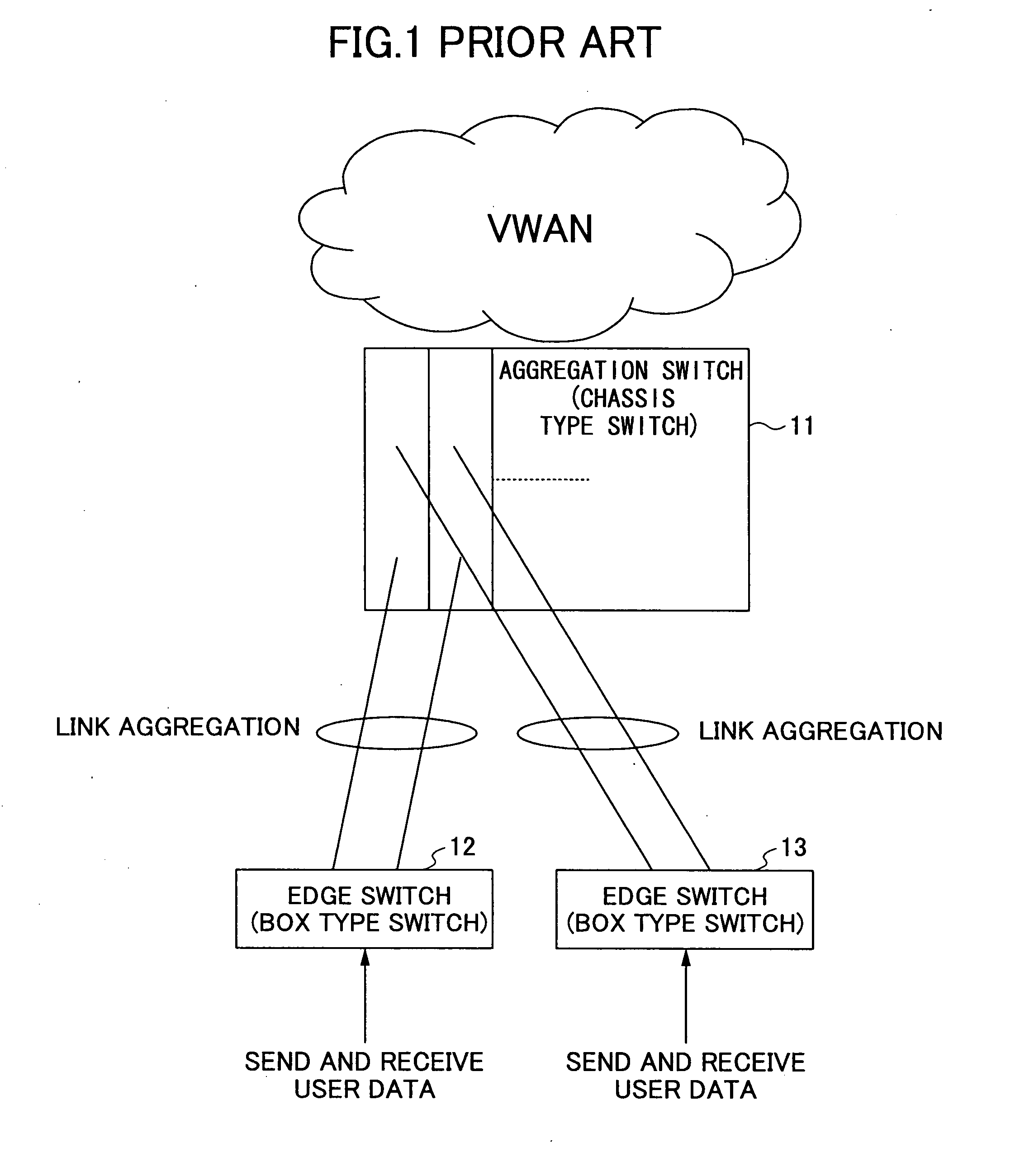
In this case, when the number of users increases, the number of the edge switches placed below increases so that the number of ports of the aggregation switch 11 may become insufficient.
When contracted bandwidth of each edge switch is narrow, there is a problem in that the number of ports lacks although switching capacity of the aggregation switch 11 is sufficient.
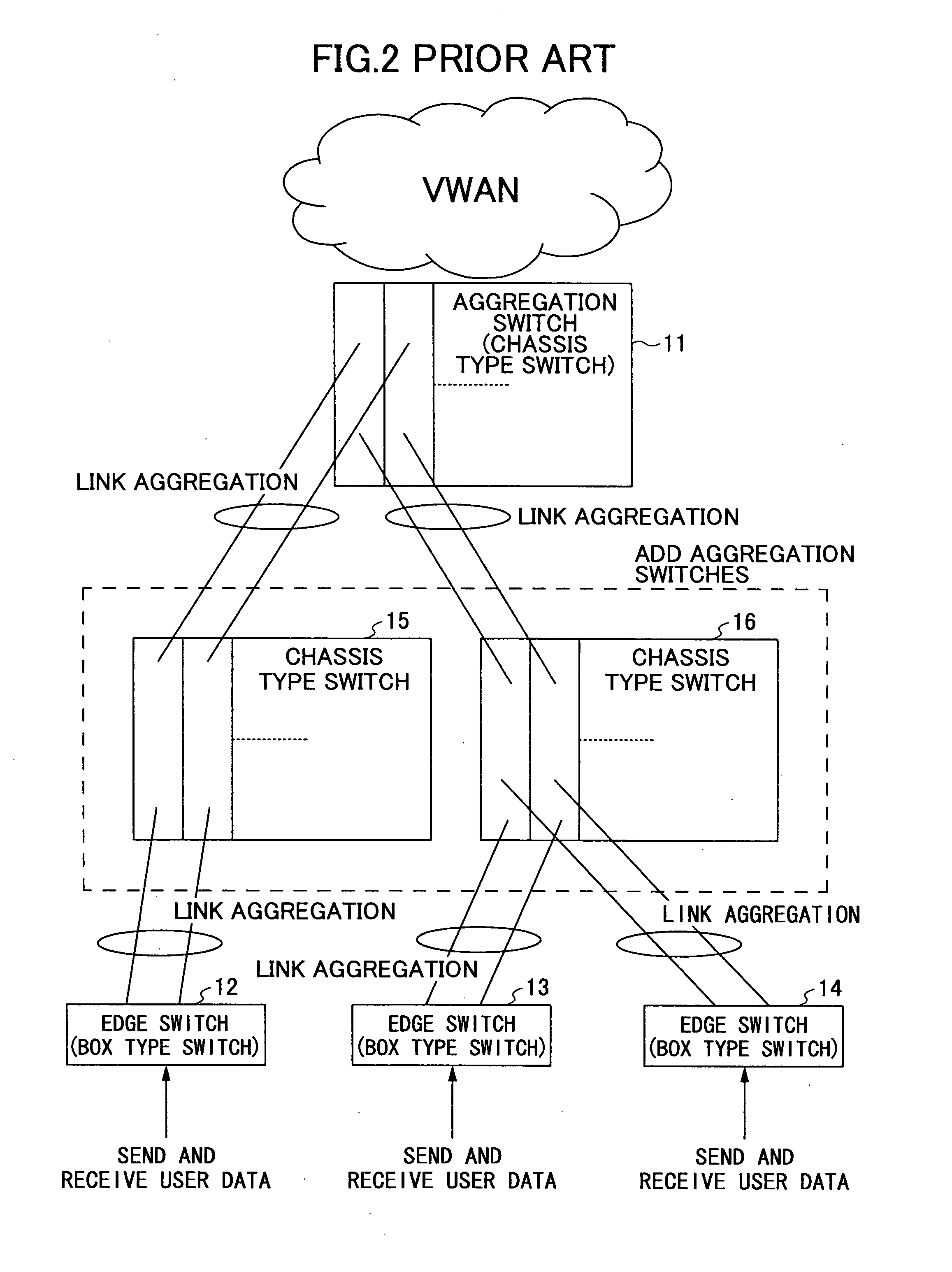
But, the added aggregation switches that are the chassis type are expensive compared with the box type switch.
In addition, since the capacity of the chassis type switch is generally large, the system may become overengineered.
In addition, when there is a surplus of switch capacity in the upper aggregation switch 11, there is a problem in that cost performance is low in terms of switch capacity.
But, for changing the network configuration from the existing tree configuration shown in FIG. 1 to the ring configuration shown in FIG. 3, there is a problem in that existing operating lines are affected.
In addition, there is a problem in that, for changing the network configuration, user lines are interrupted, or, the lines need to be aggregated using the chassis type switch that is expensive and that has no space merit.

Method used


Image

  • Network redundancy method and middle switch apparatus
  • Network redundancy method and middle switch apparatus
  • Network redundancy method and middle switch apparatus

Examples


second embodiment

of Operation when Network Port Failure Occurs in the Box Type Switch

[0089]FIG. 10 shows a block diagram for explaining the second embodiment of operation for network port failure in the box type switch. In the figure, each number enclosed in parentheses corresponds to each number in the following description. By the way, similar operation is performed also when failure occurs such as cable disconnection in a line between the network port 32 of the box type switch and the aggregation switch 21.

[0090]When failure occurs in the port NP1 in the network port 32 in the box type switch 25, the CPU 35 of the box type switch 25 detects the failure of the port NP1. The link down unit 35e operating in the CPU 35 recognizes VLAN information set in the port NP1 of the network port 32 where the failure occurs (1), and sets each of ports AP1, AP2 and AP3 of the access port 31 to be in a link down status wherein the VLAN information is set in the ports AP1, AP2 and AP3 (2). Accordingly, the lower e...

first embodiment

of Operation for Apparatus Failure of the Box Type Switch

[0094]The first embodiment of operation for apparatus failure of the box type switch is described with reference to FIG. 10. When apparatus failure occurs in the box type switch 25, the CPU 35 of the box type switch 25 detects it. The CPU 35 changes the state of every port of the access port 31 and the network port 32 into a link down state, and stops sending the keep alive packet from the redundant port 33 to another box type switch 26.

[0095]The another box type switch 26 detects that the keep alive packet is stopped so as to report it to an operator.

[0096]

[0097]In the system of the present embodiment, when performing in-band monitoring in which monitoring information of a carrier is multiplexed to a transmission channel where user traffic is carried, each of the aggregation switch 21 and edge switches 22 and 23 does not necessarily transfer an in-band monitoring frame addressed to the box type switch 25 to the box type switc...


PUM


Abstract

Each of an upper switch apparatus and lower switch apparatuses is connected to ports of a same port number of a pair of middle switch apparatuses by setting link aggregation, the pair of the middle switches are connected to each other via redundancy ports. When failure occurs at a port, connected to the lower switch apparatus, of one middles switch apparatus of the pair, the one middle switch apparatus adds input port information to a frame addressed to the failed port to transfer the frame to another middle switch apparatus of the pair from the redundancy port, and the another middle switch apparatus receives the frame from the redundancy port and transfers the frame in accordance with the input port information added to the frame.

Description

BACKGROUND OF THE INVENTION[0001]1. Field of the Invention[0002]The present invention relates to a network redundancy method and a middle switch apparatus. More particularly, the present invention relates to a redundancy method and a middle switch apparatus in a network including an upper apparatus, a plurality of middle switch apparatuses and a plurality of lower switch apparatuses.[0003]2. Description of the Related Art[0004]A switch apparatus such as a layer 2 switch (L2SW), a layer 3 switch (L3SW) and the like includes a MAC address learning function. According to this function, when the switch apparatus receives a frame, the switch apparatus obtains (extracts) a source MAC address, and stores the source MAC address into a FDB (Forwarding Database, which can be referred to as learning table) with an input port and VLAN information that is a VLAN ID (virtual LAN ID). This operation is called “learning”.[0005]In addition, when a frame arrives, the switch apparatus obtains a destin...

Claims


Application Information

Patent Timeline
Patent Type & Authority Applications(United States)
IPC IPC(8): H04L12/24H04L45/586H04L12/44
CPCH04L12/66
Inventor MIENO, HIRONORI
Owner FUJITSU LTD
Learn More