Eureka AIR delivers breakthrough ideas for toughest innovation challenges, trusted by R&D personnel around the world.

Communication system and network relay apparatus

a communication system and relay technology, applied in electrical devices, data switching networks, digital transmission, etc., can solve the problem that the frame received from the maintenance and management terminal might not be transferred to the specific fabric switch, and achieve the effect of low cost, easy implementation, and easy increase of the number of ports

Active Publication Date: 2015-12-29
APRESIA SYST LTD
View PDF11 Cites 0 Cited by
  • Summary
  • Abstract
  • Description
  • Claims
  • Application Information

AI Technical Summary

Benefits of technology

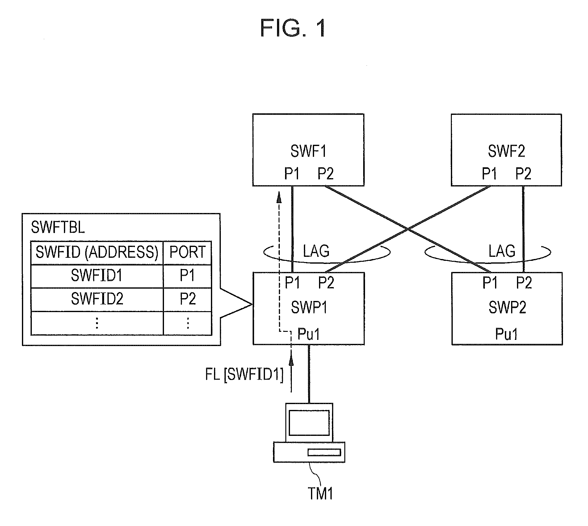
[0007]In a box-type fabric system, for example, a single port switch is connected to a plurality of fabric switches via a plurality of communication lines, and may set a single link aggregation for a plurality of ports serving as connection sources. When a link aggregation is set, load distribution and redundancy in the link aggregation may be implemented. Therefore, for example, when the communication band is to be expanded, additional fabric switches may be provided, thus allowing expansion of the communication band to be easily implemented at low costs. Furthermore, in the system, besides the expansion in communication band described above, the number of ports may be easily increased at low costs by providing additional port switches. As a result, using the system, as compared to a case where a system including chassis switch devices is used, a flexible system which meets user demands may be constructed at low costs.
[0013]An advantage of a typical embodiment of the present invention disclosed in the present application is that in-band management may be implemented in a network relay apparatus in which a link aggregation is used and a communication system including the network relay apparatus.

Problems solved by technology

However, in the port switch, a link aggregation is set for each port serving as a connection source of the communication line connected to the fabric switches, and thus, a frame received from the maintenance and management terminal might not be transferred to the specific fabric switch.

Method used


Image

  • Communication system and network relay apparatus
  • Communication system and network relay apparatus
  • Communication system and network relay apparatus

Examples


Embodiment Construction

[0018]In the embodiments described below, the invention will be described in a plurality of sections or embodiments when required as a matter of conveniences. However, unless otherwise stated, these sections or embodiments are not irrelevant to each other, and the one relates to the entire or a part of the other as a modification example, details, or a supplementary explanation thereof. Also, in the embodiments described below, when referring to the number of elements (including the number of pieces, numerical value, amount, range, and so forth), the number of the elements is not limited to a specific number unless otherwise stated or except the case where the number is apparently limited to a specific number in principal. The number larger or smaller than the specific number is also applicable.

[0019]Furthermore, in the embodiments described below, it goes without saying that the components (including element steps) are not always indispensable unless otherwise stated or except the ...


PUM


Abstract

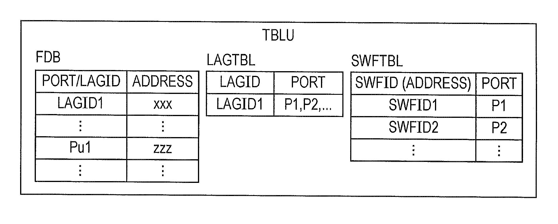
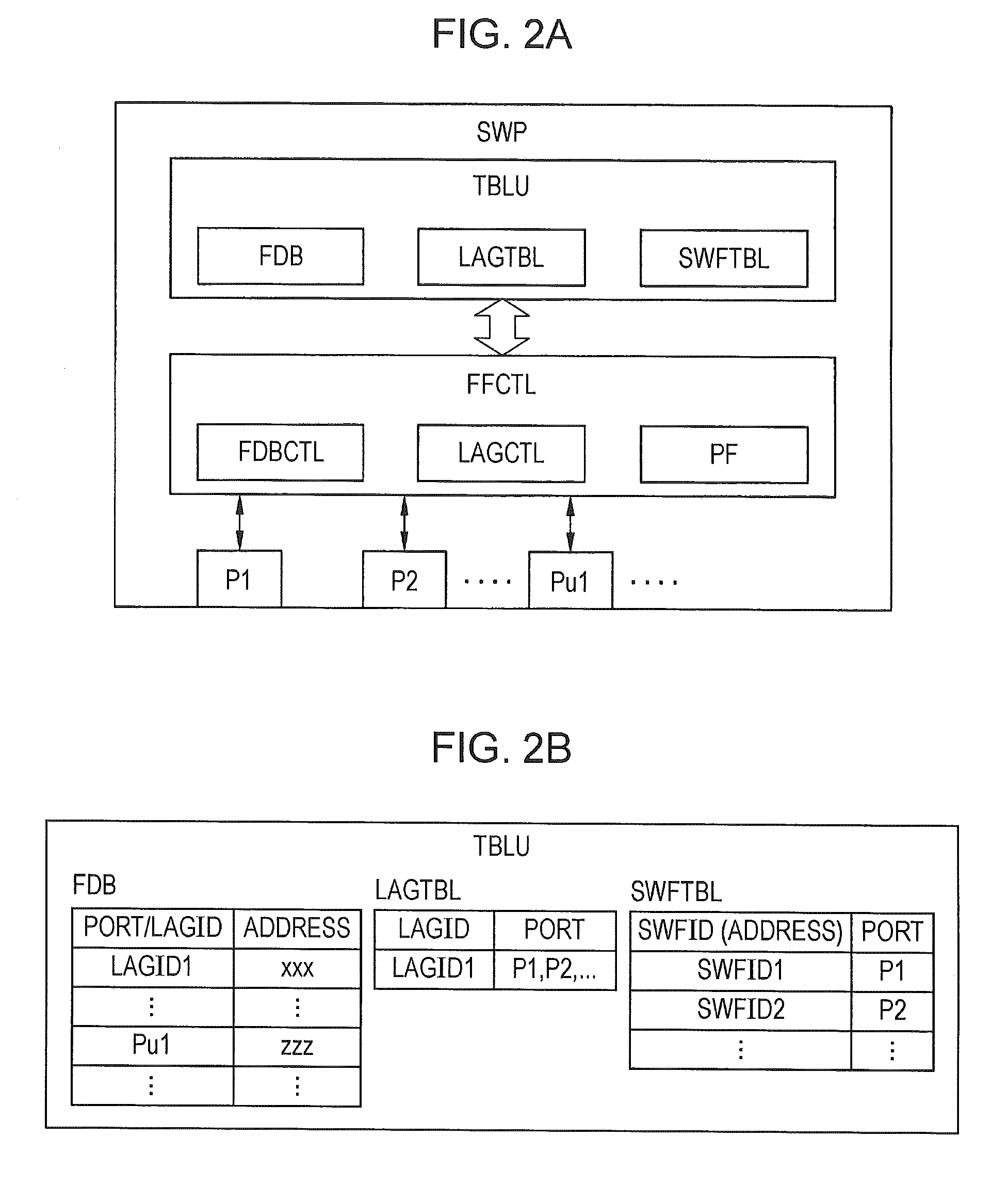
A port switch includes ports that are to serve as communication sources of communication lines extending to a plurality of fabric switches, and sets a link aggregation for the ports. The port switch further includes a fabric switch table indicating a correspondence relationship between each of the addresses of the fabric switches and the corresponding one of the ports. When the port switch receives a frame from a terminal, the port switch detects a destination address in the frame, determines, if the destination address is one of the addresses in the fabric switch table, a port corresponding to the one of the addresses, on the basis of the fabric switch table to transfer the frame from the port.

Description

[0001]The present application is based on Japanese patent application No. 2012-250327 filed on Nov. 14, 2012, the entire contents of which are incorporated herein by reference.BACKGROUND OF THE INVENTION[0002]1. Field of the Invention[0003]The present invention relates to a communication system and a network relay apparatus, and more particularly, relates to, for example, a maintenance and management technology for use in a communication system in which a link aggregation is used for communication from a single switching device to a plurality of switching devices.[0004]2. Description of the Related Art[0005]For example, Japanese Unexamined Patent Application Publication No. 2010-288168 describes a configuration including a plurality of leaf switches to each of which a terminal is connected, and a plurality of root switches each of which relays communication between the leaf switches. Each of the leaf switches is connected to the plurality of root switches via communication lines, tr...

Claims


Application Information

Patent Timeline
Patent Type & Authority Patents(United States)
IPC IPC(8): H04L12/933H04L12/935H04L47/41H04L49/111
CPCH04L49/3009H04L49/10H04L49/15H04L49/118H04L49/111
Inventor TATSUMI, TOMOYOSHI
Owner APRESIA SYST LTD
Why Eureka
Eureka Blog
Learn More