
Vehicular hydraulic system with check valve

a check valve and hydraulic system technology, applied in the direction of braking systems, braking components, transportation and packaging, etc., can solve the problems of difficulty in using vacuum assist braking systems, aftermarket demand for hydraulic braking assist systems, and ineffective use of vacuum assist systems, etc., to achieve the effect of effective and inexpensiv

Inactive Publication Date:
View PDF31 Cites 4 Cited by
  • Summary
  • Abstract
  • Description
  • Claims
  • Application Information

AI Technical Summary

Benefits of technology

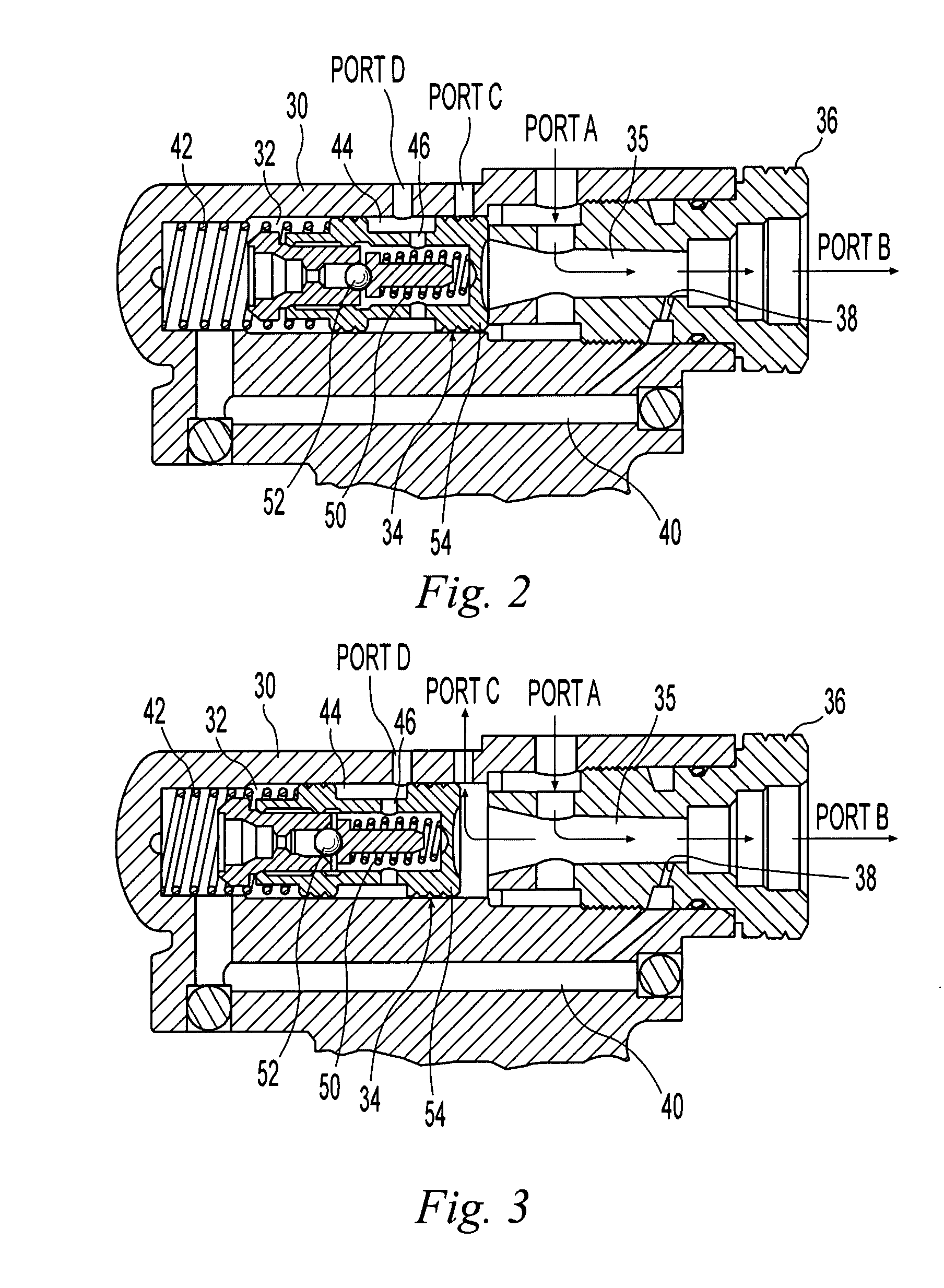
The present invention provides a hydraulic system for vehicles that ensures a relatively free flow of hydraulic fluid to a second hydraulic application arranged in series behind a first hydraulic application. This is achieved through the use of a one-way check valve parallel with the second hydraulic application, which allows fluid flow from a first point in fluid communication with the primary flow path upstream of the second hydraulic application to a second point in fluid communication with the primary flow path downstream of the second hydraulic application when fluid pressure at the first point exceeds fluid pressure at the second point by a valve-actuating differential value. The invention is effective and inexpensive and can be used in vehicles with engines.

Problems solved by technology

The use of vacuum assist braking systems can be problematic in vehicles having a turbo-charged engine and such vehicles will also often employ hydraulic braking assist systems.
Furthermore, there is an aftermarket demand for hydraulic braking assist systems for vehicles, such as hotrods, that may not otherwise have a brake assist device or for which the use of a vacuum assist system presents difficulties.
Because of the series arrangement, the application of the brakes and engagement of the hydraulic braking assist system can affect the flow of hydraulic fluid to the steering gear, thereby affecting the amount of assist available to the steering gear.
During this relief condition, a diminished flow of fluid is sent to the steering gear which may result in a detectable increase in steering effort by the operator of the vehicle to turn the steering wheel under extreme relief conditions.

Method used


Image

  • Vehicular hydraulic system with check valve
  • Vehicular hydraulic system with check valve
  • Vehicular hydraulic system with check valve

Examples


Embodiment Construction

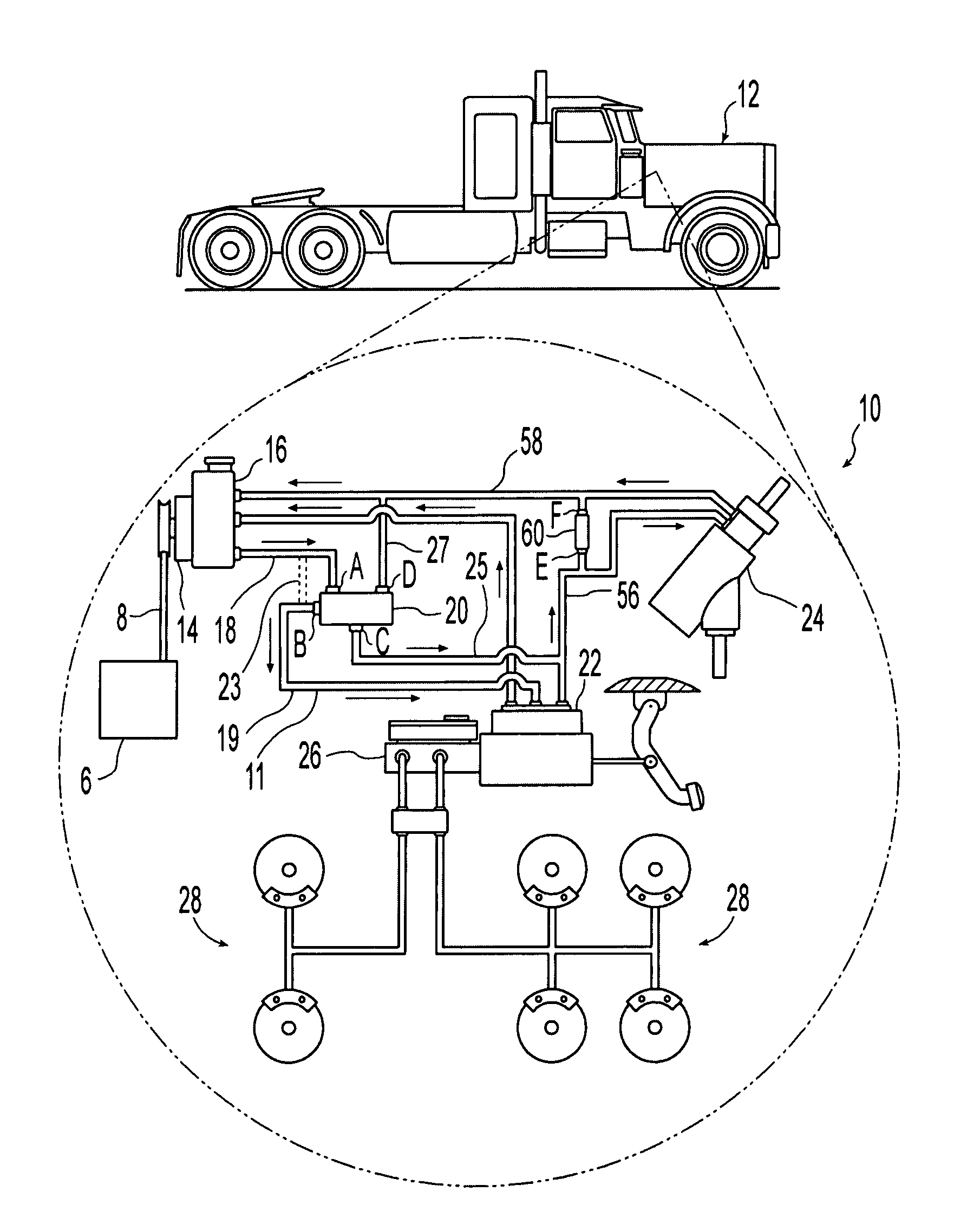
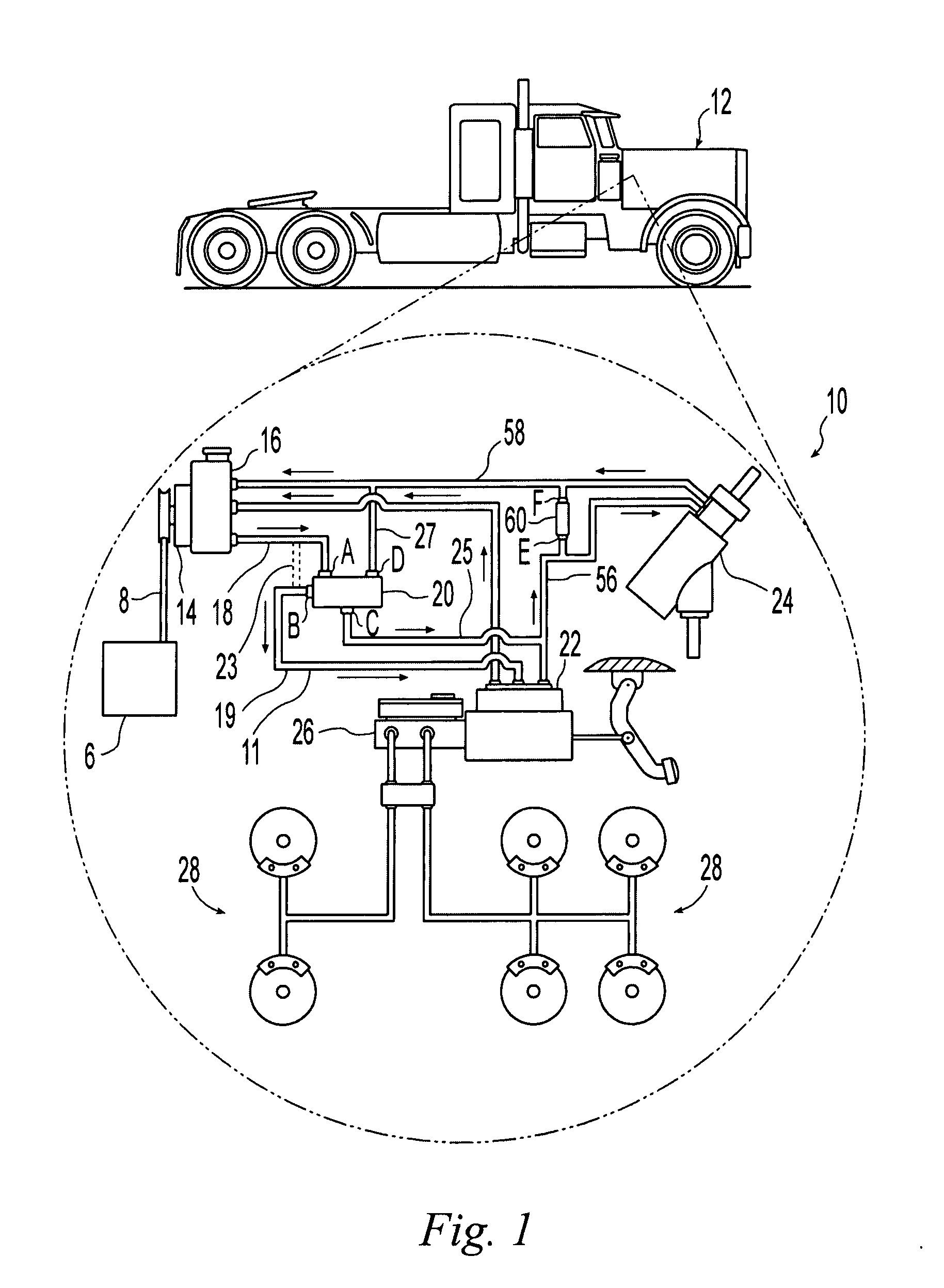
[0021]FIG. 1 shows a hydraulic system 10 for a vehicle 12 for assisting in the steering and braking of the vehicle. The hydraulic system includes a hydraulic pump 14 and reservoir 16. The reservoir may be incorporated into the pump 14, as illustrated, or may be located remote from the pump 14. In the illustrated embodiment, and as schematically depicted in FIG. 1, hydraulic pump 14 is operably coupled with the engine 6 of vehicle 12 with a belt 8.

[0022]The illustrated pump 14 is a conventional hydraulic pump and includes a flow control feature such that above a predefined operating speed of engine 6, pump 14 will discharge hydraulic fluid into discharge line 18 at a discharge rate that falls within a predefined range. FIG. 5 presents an idealized graph depicting the discharge rate of pump 14 plotted against the rotational speed of engine 6. Those having ordinary skill in the art will also recognize that the graph depicted in FIG. 5 is an idealized graph and the actual output of a hy...


PUM


Abstract

A vehicular hydraulic system having a hydraulic pump, a first hydraulic application, a second hydraulic application and a hydraulic reservoir arranged in series. A check valve is positioned to allow the flow of fluid from a point between the second hydraulic application and the pump to a point upstream of the second hydraulic application when the fluid flow upstream of the second application has been significantly reduced. The first and second applications may be a hydraulic brake assist device and a steering gear assist device. The use of such a check valve may also be employed with a hydraulic system having a priority valve for diverting a portion of the fluid flow to the second application when the pressure upstream of the first application is elevated above a threshold value. The hydraulic system may also employ a pump that has a discharge rate that falls within a predefined range.

Description

CROSS REFERENCE TO RELATED APPLICATIONS[0001]This application claims priority under 35 U.S.C. 119(e) of U.S. provisional patent application Ser. No. 60 / 845,899 filed on Sep. 20, 2006 entitled VEHICULAR HYDRAULIC SYSTEM WITH CHECK VALVE the disclosure of which is hereby incorporated herein by reference.BACKGROUND OF THE INVENTION[0002]1. Field of the Invention[0003]The present invention relates to hydraulic systems for vehicles and, more particularly, to a hydraulic system having a hydraulic fluid pump and at least two hydraulic applications.[0004]2. Description of the Related Art[0005]Many trucks with hydraulic braking systems, particularly larger gasoline powered and diesel powered trucks, incorporate hydraulic braking assist systems, rather than vacuum assist systems commonly found in passenger automobiles. The use of vacuum assist braking systems can be problematic in vehicles having a turbo-charged engine and such vehicles will also often employ hydraulic braking assist systems....

Claims


Application Information

Patent Timeline
Patent Type & Authority Applications(United States)
IPC IPC(8): B60T13/14B60T17/02B62D5/07
CPCB60T13/165B62D5/075B62D5/07
Inventor WONG, ALBERT C.WONG, TOM C.LINCOLN, RICK L.DAVISON, JAMES L.
Learn More