
Wave Gear Device

a gear device and wave technology, applied in the direction of gearing, toothed gearing, belt/chain/gearing, etc., to achieve the effect of simple shape and easy work

Inactive Publication Date: 2008-03-13
NABLESCO CORP
View PDF3 Cites 16 Cited by
  • Summary
  • Abstract
  • Description
  • Claims
  • Application Information

AI Technical Summary

Benefits of technology

[0011] By this constitution, the wave gear device of the invention has the simple shape in the thinnest portion so that the external tooth gear can be easily worked.

Problems solved by technology

This raises a problem that what can be transmitted is a torque at such a level that the diaphragm is not broken by the stress concentrated at the diaphragm.

Method used


Image

  • Wave Gear Device
  • Wave Gear Device
  • Wave Gear Device

Examples


first embodiment

[0019] At first, the constitution of a wave gear device according to a first embodiment is described.

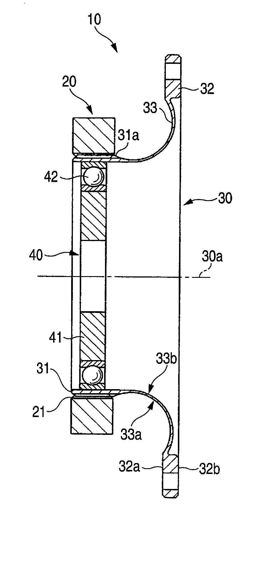
[0020] As shown in FIG. 1, a silk hat type wave gear device 10 is provided with: a thick circular spline 20 acting as an annular internal tooth gear having internal teeth 21 formed thereon; a silk hat shaped flex spline 30 as a flexible external tooth gear having an external tooth portion 31 having external teeth 31a formed to mesh partially with the internal teeth 21 and arranged on the inner side of the circular spline 20; and a wave generator 40 arranged on the inner side of the flex spline 30 and acting as a wave generator for rotating the flex spline 30 with respect to the circular spline 20 while warping the flex spline 30.

[0021] The flex spline 30 includes a boss portion 32 as a fixed portion to be fixed on the not-shown external member, and a connecting portion 33 for connecting the external tooth portion 31 and the boss portion 32.

[0022] On the other hand, the wave genera...

second embodiment

[0031] At first, the constitution of a wave gear device according to a second embodiment is described.

[0032] Of the constitutions of the wave gear device according to this embodiment, a constitution like that of the silk hat type wave gear device 10 (as referred to FIG. 1) according to the first embodiment is omitted on its detailed description by designating it with reference numerals similar to those of the constitution of the silk hat type wave gear device 10.

[0033] As shown in FIG. 3, a cup type wave gear device 60 as the wave gear device according to this embodiment is similar to such a constitution that the silk hat type wave gear device 10 is provided with, in place of the flex spline 30 (as referred to FIG. 1), a thin cup-shaped flex spline 80 including an external tooth portion 81 having an external teeth 81a meshing partially with the internal teeth 21 and acting as a flexible external tooth gear arranged on the inner side of the circular spline 20.

[0034] The flex splin...


PUM


Abstract

Provided is a wave gear device capable of transmitting a high torque. The silk hat type wave gear device comprises an annular circular spline having internal teeth formed thereon; a flexible flex spline having external teeth formed to mesh partially with the internal teeth and arranged on the inner side of the circular spline; and a wave generator arranged on the inner side of the flex spline. The flex spline includes a boss portion adapted to be fixed on an external member, and a connecting portion for connecting the external tooth portion and the boss portion. The connecting portion is so shaped that a sectional shape when cut in a plane extending through an axis of rotation of the flex spline is gradually reduced in thickness toward the substantial center from the side of the external tooth portion and the side of the boss portion.

Description

CROSS-REFERENCE TO RELATED APPLICATIONS [0001] This application is a Section 371 of International Application No. PCT / JP2005 / 018028, filed Sep. 29, 2005, which was published on Jun. 4, 2006, under International Publication No. WO 2006 / 035907 A1, the disclosure of which is incorporated herein by reference.BACKGROUND OF THE INVENTION [0002] The present invention relates to a wave gear device for transmitting a torque. [0003] In the background art, there is known a wave gear device (as referred to Patent Document 1, for example), which is provided with a flexible external tooth gear including a curved portion having a diameter gradually reduced from the side of a diaphragm toward the side of a trunk portion. [0004] Patent Document 1:JP-A-2004-28122, (Pages 3-4, FIG. 3) BRIEF SUMMARY OF THE INVENTION [0005] In the wave gear device of the background art, however, a stress is concentrated at the diaphragm by the torque transmitted from the internal tooth gear to the external tooth gear. T...

Claims


Application Information

Patent Timeline
Patent Type & Authority Applications(United States)
IPC IPC(8): F16H1/32
CPCY10T74/19F16H49/001F16H1/32
Inventor LI, SHUTING
Owner NABLESCO CORP
Learn More