Balancer

a balancer and balance technology, applied in the field of balancers, can solve the problems of reducing the grinding precision, affecting the smoothness of the rotary body, so as to facilitate the movement of the weight, reduce the vibration caused by the impact, and effectively suppress the effect of the vibration

Inactive Publication Date: 2008-03-13
AKAZAWA MACHINE
View PDF5 Cites 7 Cited by
  • Summary
  • Abstract
  • Description
  • Claims
  • Application Information

AI Technical Summary

Benefits of technology

[0011] As a result, the weight is pressed against the guide face which is positioned at the outward side in the diametrical direction and against the pressing face which is positioned at the one side in the axial direction by the centrifugal force, and thus fluctuations thereof in the axial direction caused by an impact acting upon the rotary body is prevented such that vibration in the rotary body caused by such an impact can be suppressed.
[0023] According to the present invention, a balancer which is capable of compensating unbalance in the weight distribution around the rotational axis of a rotary body and effectively suppressing vibration caused by an impact can be provided with a simple and low-cost structure.

Problems solved by technology

When an impact acts upon the aforementioned conventional grinding wheel having the balancer mechanism, a problem arises in that the weights are fluctuated in the axial direction of rotation so that the grinding wheel vibrates, thereby leading to a reduction in grinding precision.
Even if the wall faces are manufactured with a high degree of precision, it is impossible to completely eliminate fluctuations of the weights in the axial direction of rotation due to tolerance, and thus improvement in the grinding precision is inhibited.
When an impact acts upon the aforementioned conventional rotary body integrated with the weight holder which is provided with the guide face having a cross section in a V-shaped groove, a problem arises in that since the weights are spherical, the weights are pressed evenly against one side and the other side of the guide face in the axial direction, thus causing the rotary body to vibrate due to fluctuations of the weight.
Therefore, in a case where a work is machined by a cutting tool which is attached to the spindle of a machine tool via a tool chuck, even if the whirling motion of the tool chuck is suppressed by the conventional balancer mechanism, the amplitude thereof increases when an impact due to a reactive force, which is caused by the cutting or an external factor such as vibration of vehicles traveling nearby roads, acts upon the tool chuck via the cutting tool; with the result that improvements in the working precision are inhibited and noise is generated from the bearing of the spindle, leading to a decrease in the longevity of the bearing.
When liquid is used in place of such weights, vibration in the grinding wheel caused by the impact can be attenuated by the flow of the liquid, but liquid with a large specific gravity is expensive and difficult to handle, causing an increase in costs.

Method used


Image

  • Balancer
  • Balancer
  • Balancer

Examples


Embodiment Construction

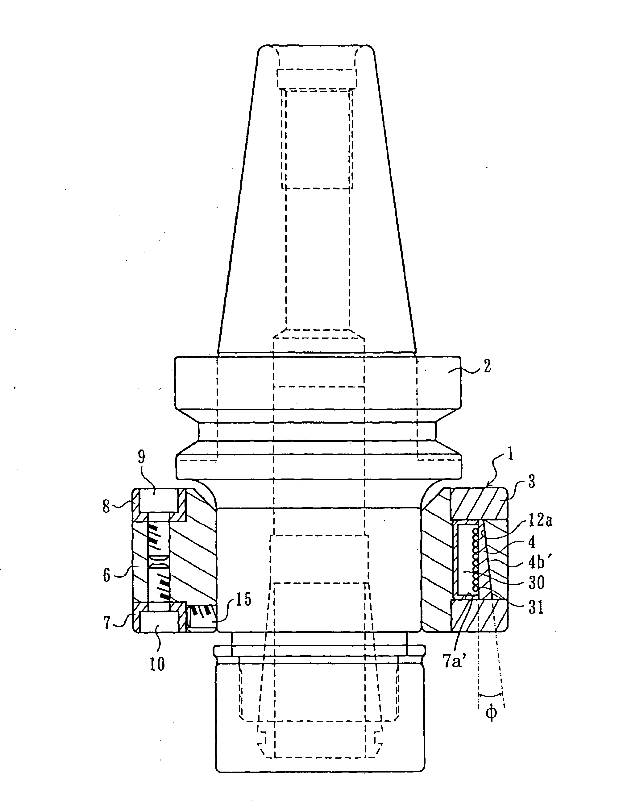
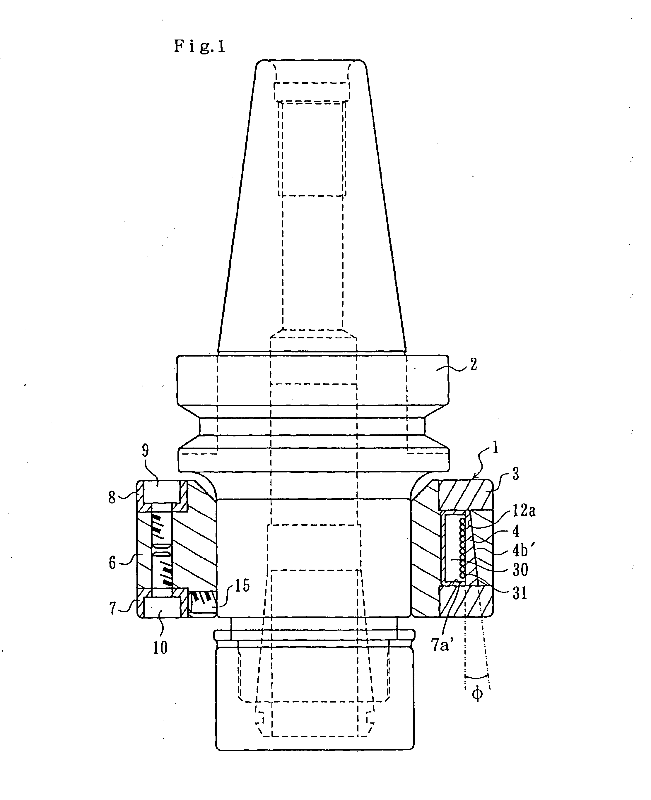
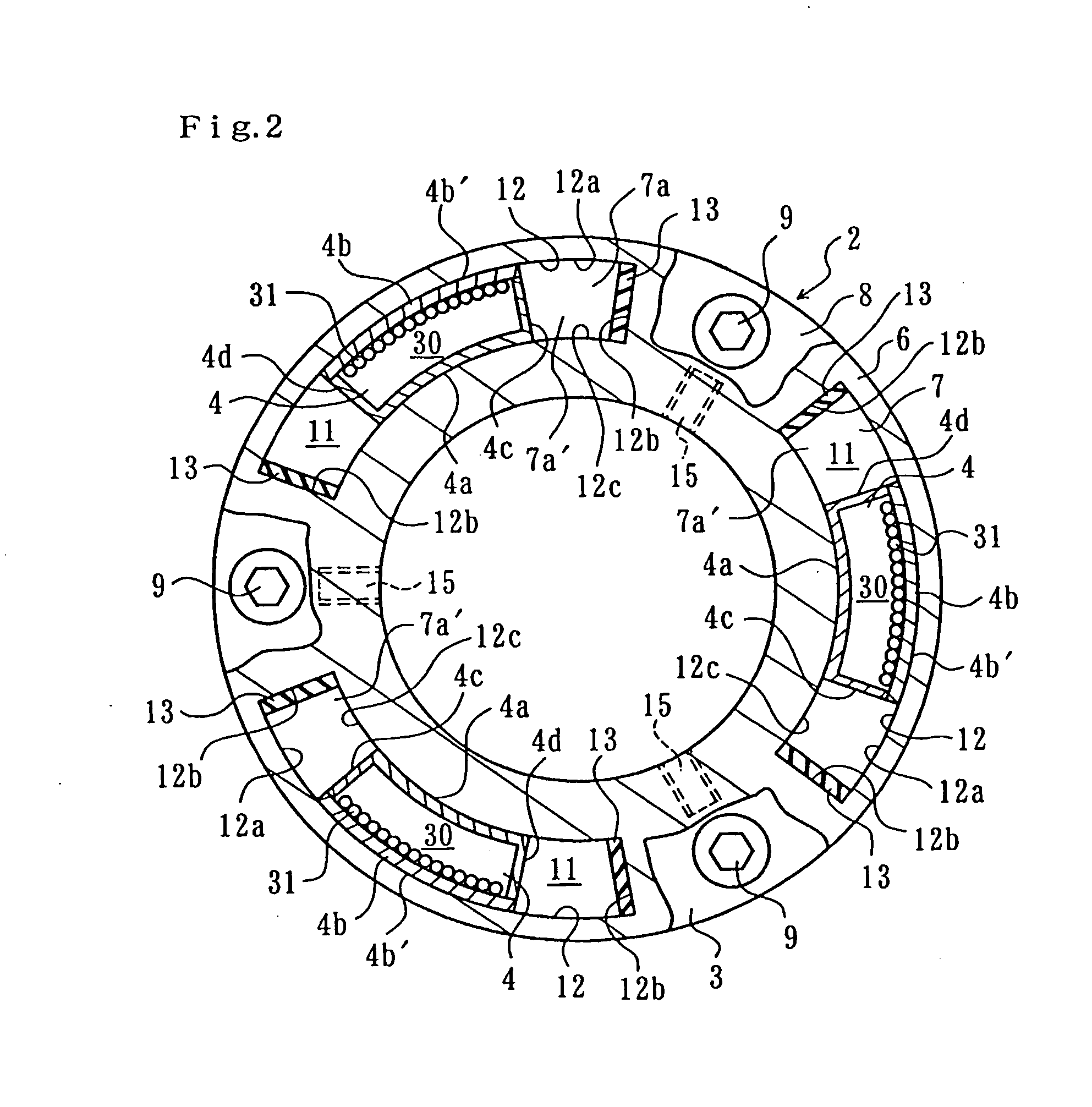
[0034] A balancer 1 illustrated in FIGS. 1 and 2 is integrated with a tool chuck (rotary body) 2 which is attached to a spindle of a machine tool, and comprises an annular weight holder 3 which is fitted on the outer circumference of the tool chuck 2 and a plurality of weights 4 which are held by the weight holder 3. In this embodiment, the number of weights 4 is set at three, but there are no particular limitations.

[0035] The weight holder 3 has a holding ring 6 and a pair of pinch rings 7, 8, the inner and outer circumferences of each of which extend along a cylinder side. As for the dimensions of the holding ring 6 in the axial direction, the inner side is longer than the outer side. As shown in FIG. 3, the holding ring 6 is sandwiched between the two pinch rings 7, 8 from its two end faces of the outer side. The holding ring 6 and pinch rings 7, 8 are connected by bolts 9, 10, and thus the holding ring 6 and pinch rings 7, 8 are integrated.

[0036] A plurality of spaces 11, the ...


PUM

PropertyMeasurementUnit
weightaaaaaaaaaa
centrifugal forceaaaaaaaaaa
distanceaaaaaaaaaa

Abstract

A weight 4 which is held by a weight holder 3 in a balancer has a pressing face 4b′ which is pressed against a guide face 12a provided along the circumferential direction of rotation of the weight holder 3 by centrifugal force generated by rotation of a rotary body. When the rotary body rotates, the weight 4 which is pressed against the guide face 12a via the pressing face 4b′ changes its position relative to the rotary body in the circumferential direction of rotation, whereby the weight 4 is disposed in a position in which it suppresses whirling motion of the rotary body. The guide face 12a and pressing face 4b′ are inclined relative to the axial direction of rotation so as to tend to outward side in the diametrical direction of rotation as tending to one side in the axial direction of rotation. The weight 4 is pressed against a receiving portion 7a′ by component of the centrifugal force, in which the component acts along the guide face 12a and pressing face 4b′.

Description

TECHNICAL FIELD [0001] The present invention relates to a balancer for suppressing whirling motion of a rotary body, such as a spindle of a machine tool, a tool chuck for holding a tool which is attached to the spindle for performing cutting or grinding, a vehicle axle, a crankshaft of an engine and others. BACKGROUND ART [0002] A grinding wheel disclosed in Japanese Patent Laid-Open Publication No. H6-198564 is provided with a balancer mechanism to compensate for unbalance in weight distribution around its rotational axis. More specifically, this grinding wheel has a storage chamber and weights which are stored in the storage chamber. The inner surface of the storage chamber has a guide face which extends along the circumferential direction of rotation and wall faces disposed in one and the other of the axial directions. Each weight has a pressing face which is pressed against the guide face by means of centrifugal force generated by rotation of the grinding wheel. When the grindin...

Claims


Application Information

Patent Timeline
Patent Type & Authority Applications(United States)
IPC IPC(8): F16F15/32B23B31/00B23Q11/00F16F15/14F16F15/31F16F15/36
CPCB23B31/00B23B2250/04B23B2250/16B23Q11/0035F16F15/145F16F15/31Y10T279/17965Y10T74/2111Y10T74/2121Y10T74/213Y10T409/304312Y10T74/2114Y10T74/2122F16F15/36
Inventor YAMAMOTO, HIROAKI
Owner AKAZAWA MACHINE
Why Eureka
Try Eureka