
X-ray tubes and methods of making the same

a technology of x-ray tubes and x-ray tubes, which is applied in the direction of x-ray tube bearing assembly cooling, electrical equipment, electric discharge tubes, etc., can solve the problems of limiting the output power of x-rays and the continuous operation of x-ray tubes, inefficient heat removal of shafts, and elevated temperatures at the contact points or asperity contacts of shafts and bearings

Inactive Publication Date: 2008-03-06
GENERAL ELECTRIC CO
View PDF16 Cites 12 Cited by
  • Summary
  • Abstract
  • Description
  • Claims
  • Application Information

AI Technical Summary

Benefits of technology

"The present patent describes a new design for a bearing assembly and a cooling solution for use in an X-ray tube. The bearing assembly includes an inner ring, an outer ring, and rolling contact elements, with at least one of the inner ring, outer ring, or rolling elements having a solid lubricant coating. The cooling solution includes a gallium-based coolant that is in contact with the rolling contact elements. The new design reduces friction and wear between the bearing components, leading to improved performance and reliability of the X-ray tube."

Problems solved by technology

This very small area of contact for thermal conduction may result in inefficient heat removal from the shaft.
Inefficient heat escape from the shaft may, in turn, result in limiting the input power on the target, which is connected to the shaft, ultimately resulting in limiting output power of the X-rays and the continuous operation of the X-ray tube.
Furthermore, disadvantageously, inefficient escape of the heat from the shaft may also result in elevated temperatures at the contact points or asperity contacts of the shaft and the bearings.
Such heat can effectively reduce the expected useful life of the tube.
However, the elevated temperatures at the asperity contacts may impair the capability of the solid lubricant to effectively lubricate the bearing components, seriously reducing the operating life of the bearings.
However, silver lubricated bearings have high wear rates at elevated temperatures due to welding at asperity contacts.
Occasionally, gallium may be employed as a lubricant, but due to its corrosive nature and low lubrication capability (film thickness), gallium as a lubricant results in excessive wear of the bearings.

Method used


Image

  • X-ray tubes and methods of making the same
  • X-ray tubes and methods of making the same
  • X-ray tubes and methods of making the same

Examples


Embodiment Construction

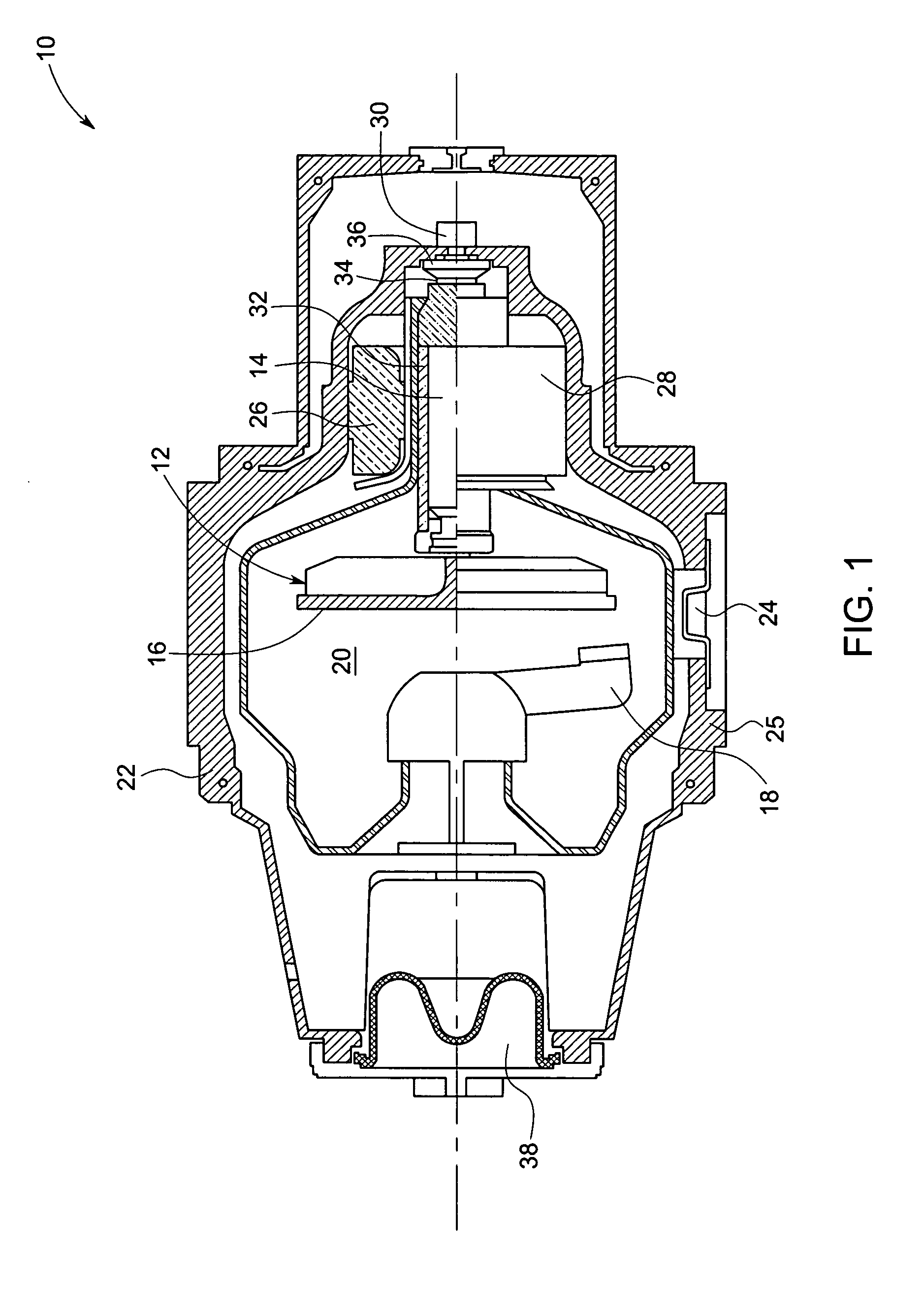
[0015]The present technique is generally directed to X-ray tubes. Particularly, the invention relates to bearings used in X-ray tubes, and to arrangements designed to enhance heat dissipation in X-ray tubes. X-ray tubes may be used in variety of applications, such as in imaging systems, particularly for medical imaging and baggage or package screening. Though the present discussion provides examples in a medical imaging context, one of ordinary skill in the art will readily comprehend that the application of these X-ray tubes in other settings, including non-medical imaging contexts, such as for security screening, is well within the scope of the present technique.

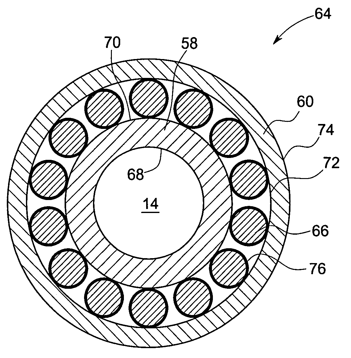
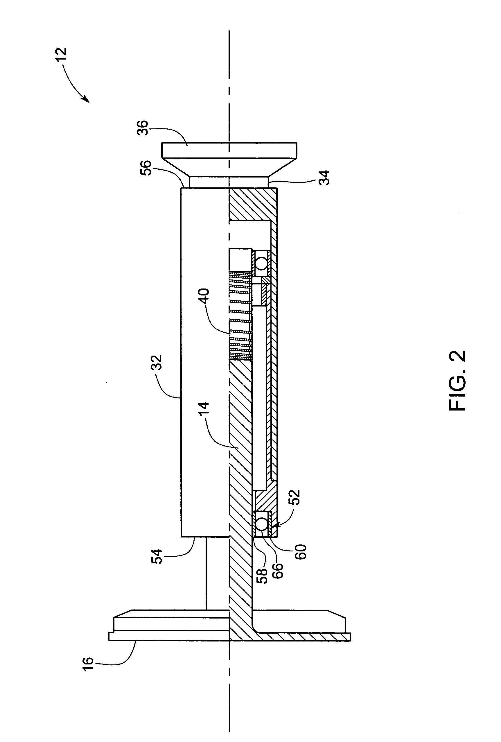
[0016]Referring now to FIG. 1, a rotating anode X-ray tube 10 is depicted. The X-ray tube 10 may be employed in medical diagnostic systems for providing a focused beam of X-ray radiation. The tube 10 includes a rotating anode assembly 12. The anode assembly 12 includes a cylindrical body or shaft 14. The shaft 14 is couple...


PUM


Abstract

A rolling contact bearing assembly is provided. The bearing assembly includes an inner ring and an outer ring concentrically disposed about the inner ring. The bearing assembly further includes a plurality of rolling contact elements disposed between the inner and outer rings, where at least one of the inner ring, the outer ring and the rolling elements having a solid lubricant coating disposed thereon. The bearing assembly further includes a gallium-based cooling solution disposed between the inner and outer rings and in contact with the rolling contact elements.

Description

BACKGROUND[0001]The invention relates generally to an X-ray tube. In particular, the invention relates to bearings used in X-ray tubes, and to arrangements designed to enhance heat dissipation in an X-ray tube and thereby to enhance the life of the bearings.[0002]In X-ray tubes having rotating anodes, the heat of the shaft is conducted from and thus removed from the shaft through the shaft bearings. The heat is eventually conducted to the bearing housing through only very small surfaces of contact between races and balls of the bearings. This very small area of contact for thermal conduction may result in inefficient heat removal from the shaft. Inefficient heat escape from the shaft may, in turn, result in limiting the input power on the target, which is connected to the shaft, ultimately resulting in limiting output power of the X-rays and the continuous operation of the X-ray tube. Furthermore, disadvantageously, inefficient escape of the heat from the shaft may also result in el...

Claims


Application Information

Patent Timeline
Patent Type & Authority Applications(United States)
IPC IPC(8): H01J35/00
CPCH01J35/101H01J2235/1046H01J2235/1295H01J2235/1208H01J2235/1086H01J35/1024
Inventor JOSHI, PRASADSAMPATH, SRINIDHILEMARCHAND, GWENAELROUZOU, ISABELLE BERANGERE
Owner GENERAL ELECTRIC CO
Learn More