
Re-transmission control method and relay station apparatus in a relay communication system

a relay communication system and relay control technology, applied in multiplex communication, frequency-division multiplex, instruments, etc., can solve the problems of ineffective use of wireless transmission resources, difficulty in expanding the wireless area that can be covered by a single wireless base station, and delay in the process of the mobile station (ms)

Inactive Publication Date: 2008-03-06
FUJITSU LTD
View PDF10 Cites 87 Cited by
  • Summary
  • Abstract
  • Description
  • Claims
  • Application Information

AI Technical Summary

Benefits of technology

The present invention provides a method and apparatus for re-transmitting data between a transmitting station and a receiving station via a relay station. The method includes detecting errors in data blocks, updating control data, preventing the error-detected data block from being transferred, transferring updated control data and remaining data blocks, generating a negative response signal, storing the negative response signal, combining the negative response signal with an affirmative response signal, and transmitting the combined response signal to the transmitting station. The technical effects of the invention include improving data transmission accuracy and reliability, reducing data loss, and improving overall communication quality.

Problems solved by technology

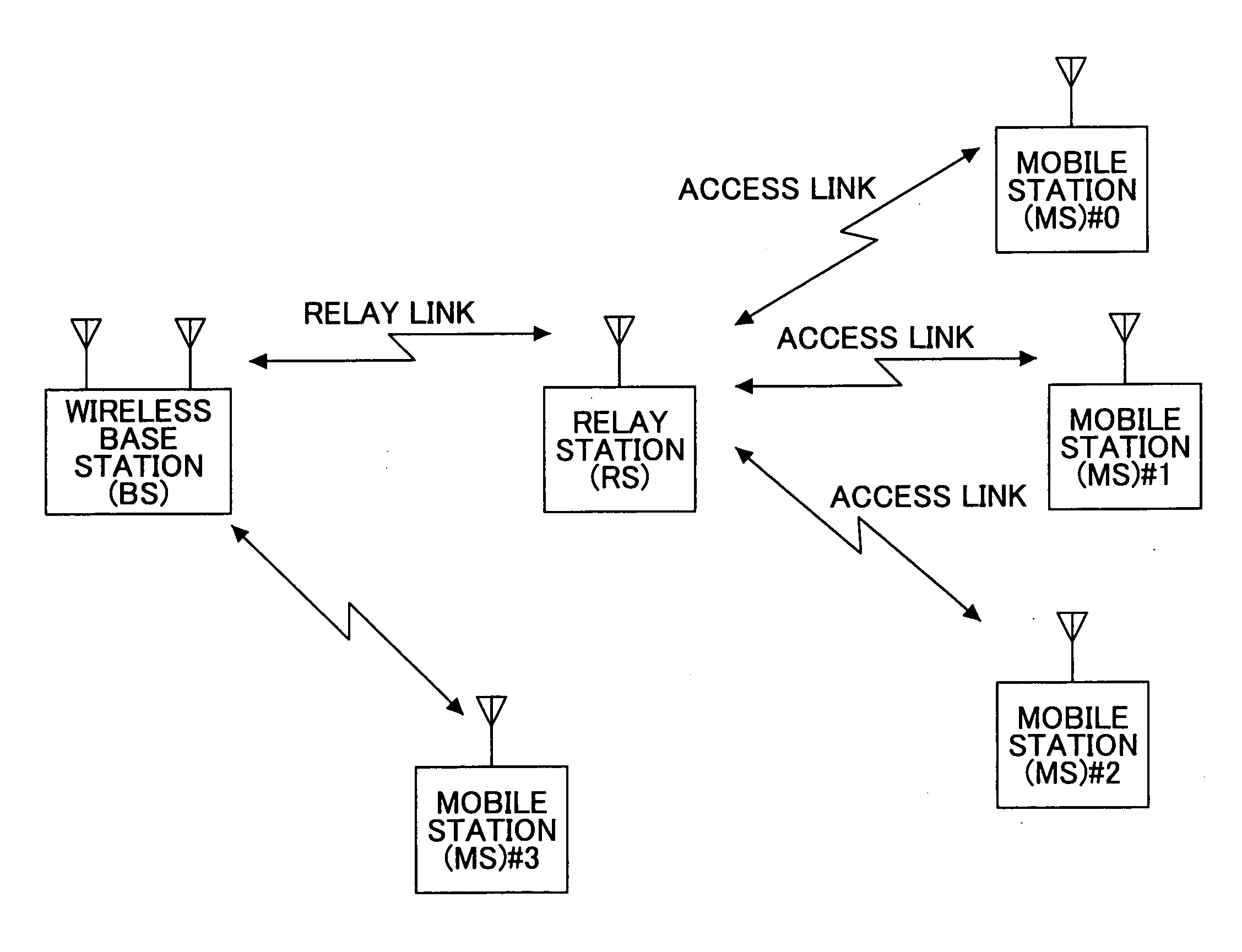
Furthermore, since transmission power of mobile stations is limited due to constraints such as their limited power capacity, it is difficult to expand the wireless area that can be covered by a single wireless base station.
Accordingly, such transmission by the relay station (RS) is a waste of transmission power and is an ineffective use of wireless transmission resources (Problem 1).
Furthermore, in such a case, processes of the mobile station (MS) become delayed since the decoding process and the error detection process are performed based on the invalid data.
Using power for performing such processes is also a waste of power (Problem 2).
Furthermore, available (empty) wireless transmission resources, which are created by preventing the error-detected data blocks from being transferred to the mobile station (MS), cannot be effectively utilized (unless some modifications are made) (Problem 3).
Therefore, even where the relay station (RS) deletes error data blocks and creates an empty (available) space in the downstream access link, the available wireless transmission resource cannot be utilized unless changes are made in the designation content of the control data.
This complicates the storing of data in the re-transmission buffer and managing the disposal of the data stored in the re-transmission buffer (Problem 4).
Furthermore, this relay transmission system has the same problem as Problem 3 in which there is no method of effectively utilizing wireless transmission resources of the downstream access link that are created when error-detected data blocks are prevented from being transferred.
This increases the size of the relay station (RS) and causes difficulty in mounting the relay station (RS).
Furthermore, since the access link is operated asynchronously with the relay link, the wireless base station (BS) is unable to have a direct grasp (comprehension) of the status of communication quality of the mobile station (MS).
Therefore, in a case where, for example, the wireless base station (BS) provides a priority class (QoS) with respect to each mobile station in the entire service area, the wireless base station (BS) does not have uniform control over its wireless resources during scheduling and assigning the wireless resources according to priority class (QoS) This makes it difficult for the wireless base station (BS) to assign wireless resources in correspondence with communication quality of the mobile station (MS) (Problem 5).

Method used


Image

  • Re-transmission control method and relay station apparatus in a relay communication system
  • Re-transmission control method and relay station apparatus in a relay communication system
  • Re-transmission control method and relay station apparatus in a relay communication system

Examples


Embodiment Construction

[0059]In the following, embodiments of the present invention are described with reference to the accompanying drawings.

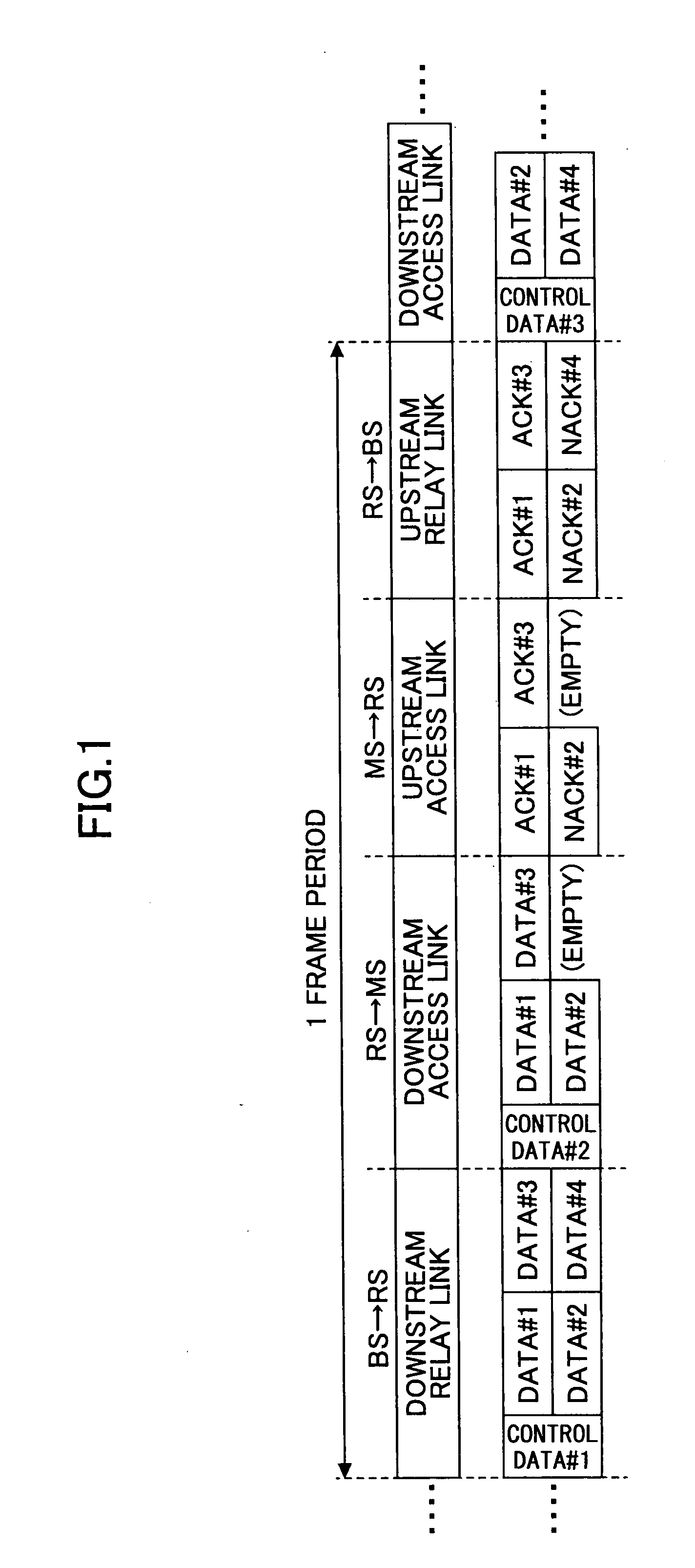
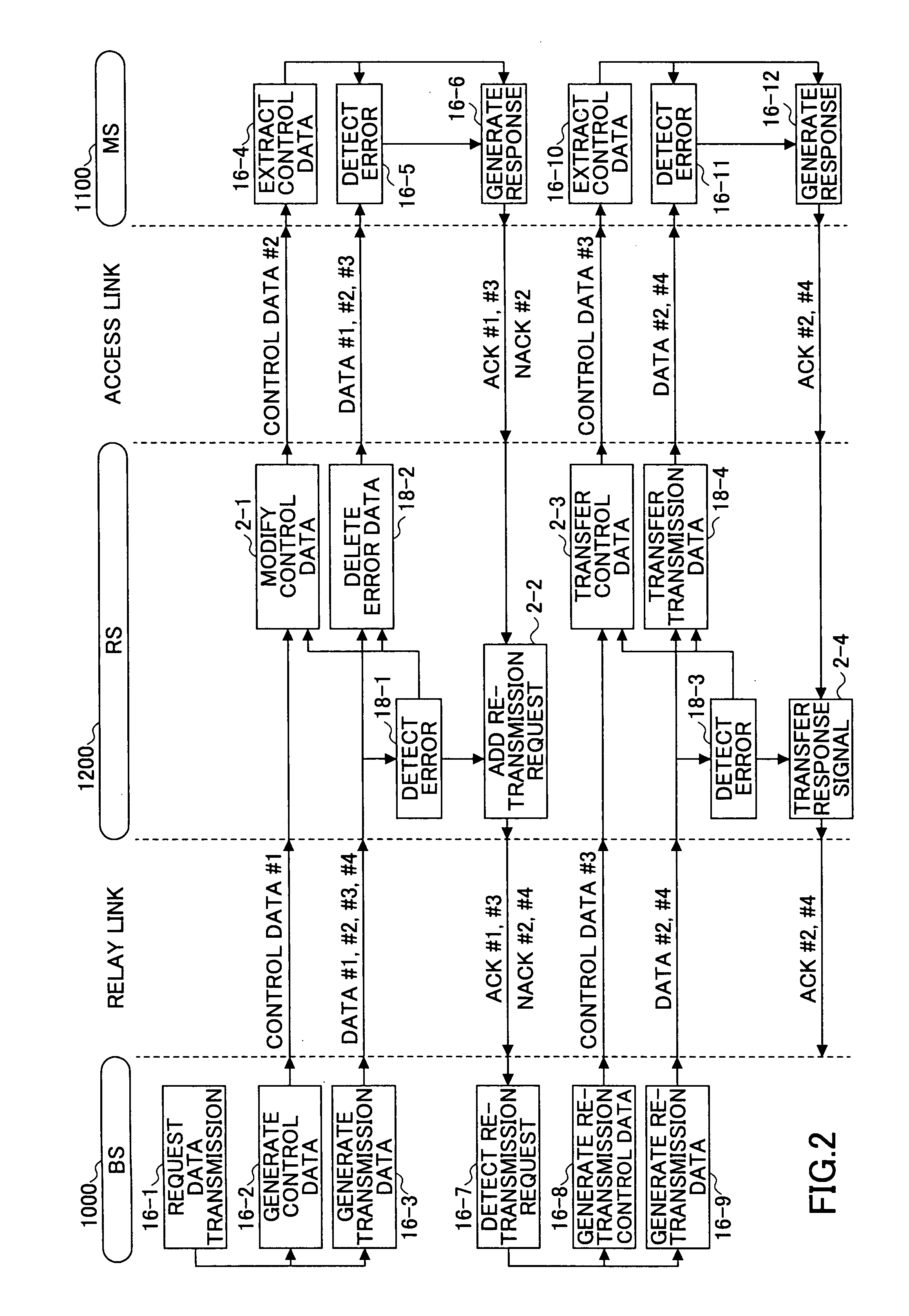
[0060]FIG. 1 is a schematic diagram showing an exemplary frame configuration in a case of performing relay communications according to an embodiment of the present invention. FIG. 2 is a sequence diagram showing data communication according to the frame shown in FIG. 1. In FIG. 2, a relay station (RS) performs error detection on data blocks received through a downstream relay link (18-1). Then, the relay station (RS) transfers errorless data blocks to a mobile station (MS) (receiving station) and prevents error-detected data blocks from being transferred to a downstream access link by deleting the error-detected data blocks (18-2). Along with preventing error-detected data blocks from being transferred, the relay station (RS) generates new control data #2 based on control data #1 received through the downstream relay link (2-1). The relay station (RS) generates (upd...


PUM


Abstract

An apparatus for relaying wireless communication between a transmitting station and a receiving station includes, parts for receiving data including control data and plural data blocks from the transmitting station, for detecting whether there is an error in the plural data blocks, part for updating the control data when an error is detected in one of the plural data blocks, for preventing an error-detected data block from being transferred to the receiving station, for transferring the updated control data and remaining data blocks to the receiving station, for generating a first negative response signal corresponding to the error-detected data block, for storing the first negative response signal, for combining the first negative response signal with an affirmative response signal or a second negative response signal received from the receiving station according to error detection results by the receiving station, and for transmitting the combined response signal to the transmitting station.

Description

BACKGROUND OF THE INVENTION[0001]1. Field of the Invention[0002]The present invention generally relates to a re-transmission control method and a relay station apparatus in a relay communication system, and more particularly to a re-transmission control method and a relay station apparatus in a relay communication system used for mobile communications.[0003]2. Description of the Related Art[0004]In recent years and continuing, there is an increasing use of mobile communications for the purpose of data communications with, for example, portable telephones and wireless LAN. Thus, wireless broadband access systems for achieving faster data communications are being studied.[0005]Compared to conventional communication systems used for purposes such as telephone communications, wireless broadband access systems are expected to provide higher wireless quality. Furthermore, since transmission power of mobile stations is limited due to constraints such as their limited power capacity, it is ...

Claims


Application Information

Patent Timeline
Patent Type & Authority Applications(United States)
IPC IPC(8): H04B7/14H04W16/26H04W28/00H04W28/04H04W84/12
CPCH04L1/0003H04L1/1628H04L1/1809H04L2001/0097H04L1/1829H04L1/1867H04L1/1819H04L1/18H04B7/14
Inventor WATANABE, MASAHIRO
Owner FUJITSU LTD
Learn More