
Method and Systems for Illuminating

Inactive Publication Date: 2008-03-06
BARCO NV
View PDF5 Cites 151 Cited by
  • Summary
  • Abstract
  • Description
  • Claims
  • Application Information

AI Technical Summary

Benefits of technology

[0023] It is an advantage of the present invention that the illumination system is relatively slim and that it can be used for high brightness applications, including LCD television.
[0024] It is also an advantage of the present invention that the illumination system combines the use of light sources having different colours with good colour uniformity.
[0025] It is furthermore an advantage of the present invention that the illumination system can be scaled up easily, without substantially influencing the luminance and / or colour uniformity qualities.
[0026] It is an advantage of some embodiments of the present invention that no mercury is present in the system, which is preferable if the system is used in medical applications.
[0027] It is an advantage of the present invention that systems can be obtained having an efficiency close to the direct backlight systems of the prior art.
[0028] The teachings of the present invention permit the design of improved methods and apparatus for providing backlight illumination in a non-emissive display system.

Problems solved by technology

However, using these light sources, such as using e.g. red, green and blue LEDs, always requires the use of an initial mixing zone for the light.
Nevertheless, the need for such a mixing zone increases the complexity of the system.
Furthermore it cannot guarantee the uniformity of brightness in the middle of the screen.
Wedge-shaped light guides are complex and furthermore induce uniformity problems in the neighbourhood of the wedge top.
The mixing zone in the air inside those complex reflectors is relatively short and therefore does not guarantee a good mixing of the colours.
In general, the brightness is limited for all edge-lit approaches as the number of light sources, e.g. LEDs, that can be provided at the edges or borders of the backlight system is limited.
Especially for large displays, the latter implies an important limit on the brightness.
Other disadvantages of these systems comprise mechanical constraints such as limitation on connecting the flex cables coming out of the panel with the LCD drivers due to the thickness and the difficulty to sink the heat generated by the LED array(s).
One disadvantage of the direct backlight system is the increased thickness of the system.
Furthermore, direct backlight systems suffer from obtaining a good luminance uniformity.
Furthermore, the centre-to-centre distance of the high power LEDs is small, which may result in heating problems and limits the possibilities to further increase the brightness by providing more light sources.
None of the above mentioned backlight systems using light sources having a different colour, allows obtaining a good colour mixing while still having a reasonable backlight thickness.

Method used


Image

  • Method and Systems for Illuminating
  • Method and Systems for Illuminating
  • Method and Systems for Illuminating

Examples


Embodiment Construction

[0041] The present invention will be described with respect to particular embodiments and with reference to certain drawings but the invention is not limited thereto but only by the claims. The drawings described are only schematic and are non-limiting. In the drawings, the size of some of the elements may be exaggerated and not drawn on scale for illustrative purposes.

[0042] Moreover, the terms top, bottom, horizontal, vertical and the like in the description and the claims are used for descriptive purposes and not necessarily for describing relative positions. It is to be understood that the terms so used are interchangeable under appropriate circumstances and that the embodiments of the invention described herein are capable of operation in other orientations than described or illustrated herein.

[0043] It is to be noticed that the term “comprising”, used in the claims, should not be interpreted as being restricted to the means listed thereafter; it does not exclude other elemen...


PUM


Abstract

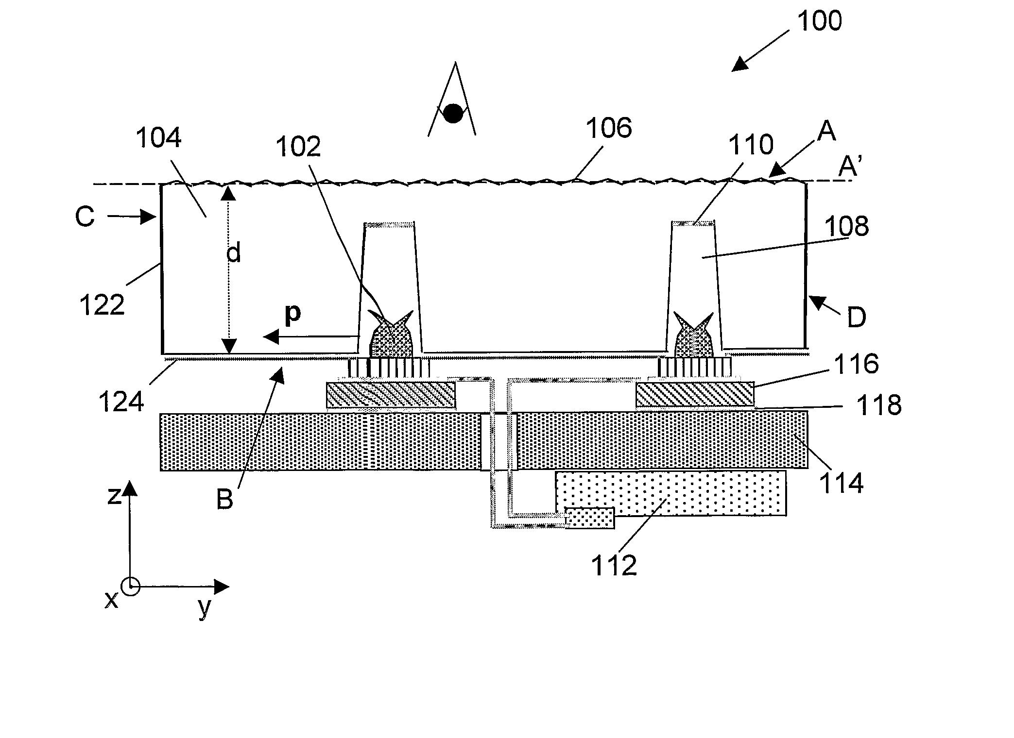
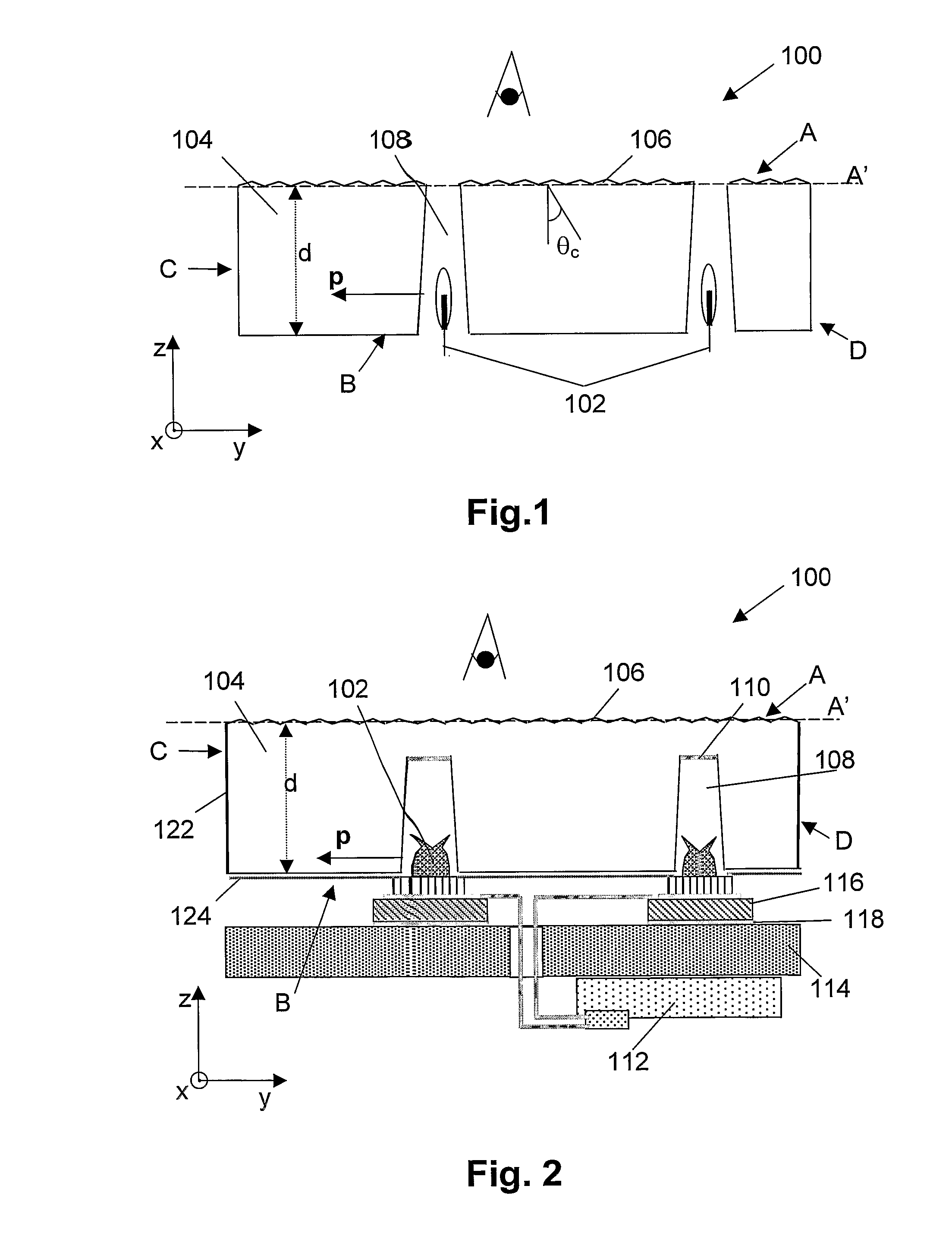
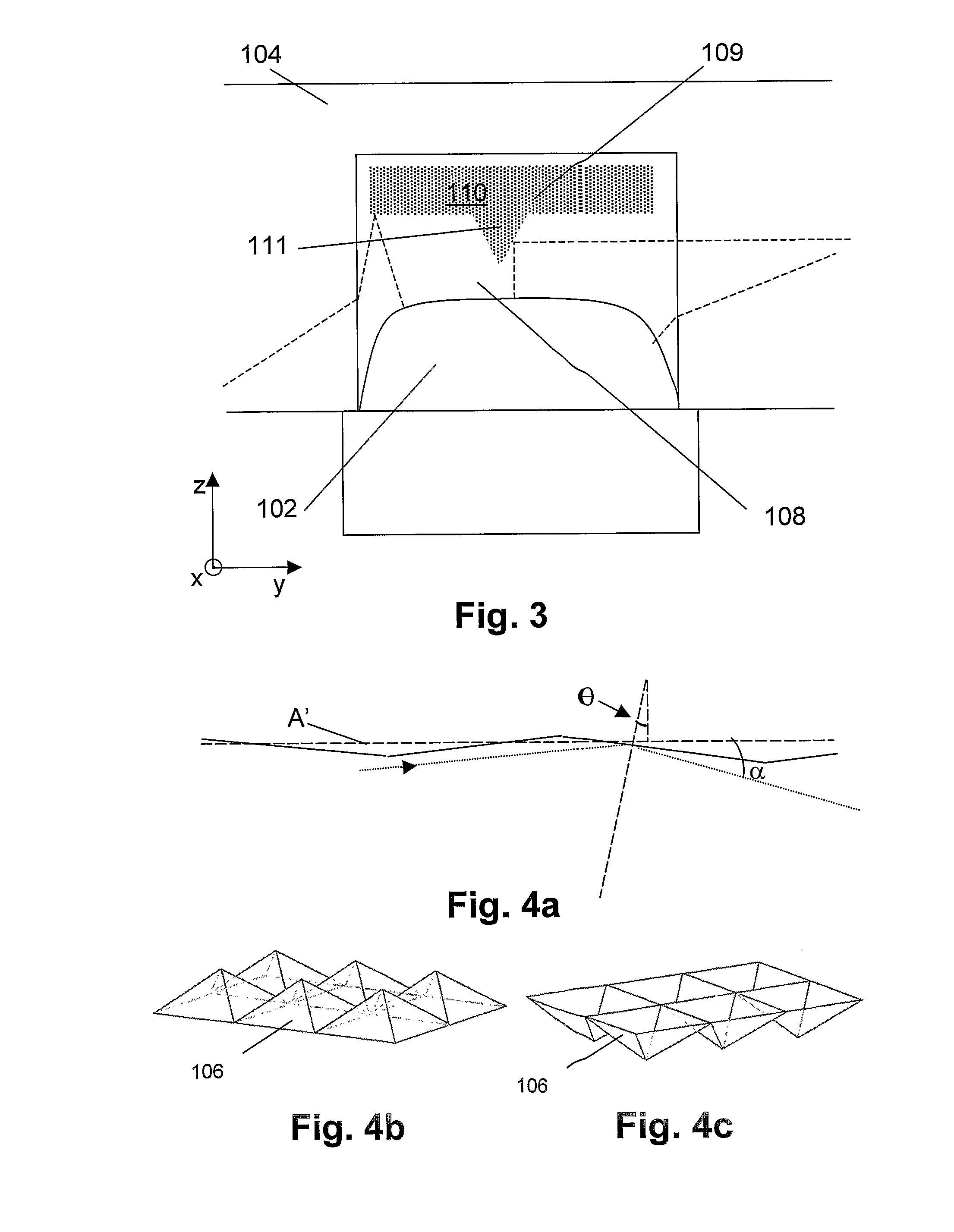
Methods and systems are described for illumination in different applications. Real thin illumination systems ( 200 ) with good luminance uniformity, good efficiency and good colour mixing uniformity are obtained, even if different light sources emitting different colours are used. A plurality of light sources ( 102 ), emitting light from different colours, couple their light sideways, i.e. substantially parallel to the plane of light out-coupling, into a light guide ( 104 ) through recesses ( 108 ) distributed over the light guide ( 104 ). Providing a specially structured surface pattern ( 106 ), in combination with light in-coupling parallel to the plane of light out-coupling of the light guide ( 104 ) allows to obtain a good colour mixing of the differently coloured light originating from the plurality of light sources ( 102 ). The light then is only coupled out after it has been in the light guide ( 104 ) for a significant long time such that the light emanating from different light sources ( 102 ) is significantly mixed. The illumination system ( 200 ) has an important application in non-emissive displays.

Description

TECHNICAL FIELD OF THE INVENTION [0001] The present invention relates to a method and system for providing illumination. More specifically, a method and system are described for illuminating applications using a thin illumination system, especially suitable as backlight system in non-emissive display systems. BACKGROUND OF THE INVENTION [0002] The display market for large illumination applications is still expanding. Applications can be found in advertising, lighting, displaying, etc. A significant segment of today's display market is focussed on thin flat panel display systems having a high brightness. The latter allows a comfortable use of the display systems for many applications, even in environments where a large amount of environmental light is present. Non-emissive flat panel displays using a backlight system as illumination source are well known and widely spread. Although, compared to traditional television systems such as cathode ray tubes, backlight illuminated flat panel...

Claims


Application Information

Patent Timeline
IPC IPC(8): F21V8/00
CPCG02B6/0021G02B6/0026G02B6/0031G02B6/0096G02B6/0041G02B6/0068G02B6/0036
Inventor VERSTRAETE, GERRITDE BRABANDER, GINO
Owner BARCO NV
Learn More