
Injection assembly for a combustor

a combustor and injection assembly technology, applied in the direction of machines/engines, mechanical equipment, lighting and heating apparatus, etc., can solve the problems of undesirable acoustic noise, increased regulation and other limits of gas turbine engines, and increased risk of combustion instability

Active Publication Date: 2008-03-06
GENERAL ELECTRIC CO
View PDF27 Cites 72 Cited by
  • Summary
  • Abstract
  • Description
  • Claims
  • Application Information

AI Technical Summary

Benefits of technology

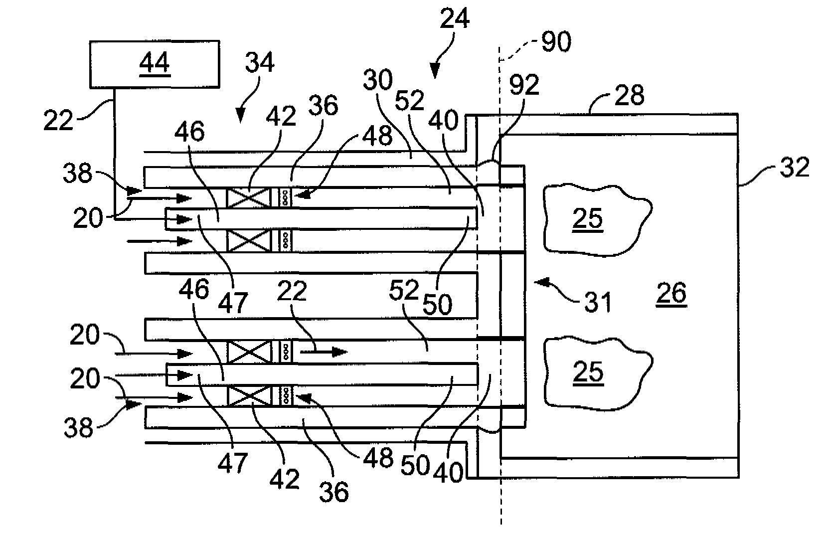
[0008]In another aspect, a method for assembling a combustor to facilitate reducing combustion dynamics in the combustor is provided. The method comprises providing at least one cap assembly having an injection assembly that includes an effusion plate with a plurality of plate openings. The injection assembly also includes a plate sleeve having a sidewall portion with a forward edge. The forward edge is coupled to the effusion plate such that the effusion plate is oriented obliquely with respect to a centerline extending through the combustor. A plurality of ring extensions are each coupled to one of the plurality of plate openings such that the ring extensions each extend into the plate sleeve. The method also includes coupling each ring extension to a premixer

Problems solved by technology

Environmental concerns regarding exhaust emissions generated from combustive processes have resulted in regulations and other limits on gas turbine engines.
However, lean premixed combustors may be more susceptible to combustion instability due to pressure oscillations in the combustion chamber.
Such instabilities can cause undesirable acoustic noise, deteriorate engine performance and reliability, and / or increase the frequency of required service.
For example, combustion instability can cause flashback, flame blowout, starting problems, damage to combustor hardware, switchover problems, High Cycle Fatigue (HCF) of hot gas path components, and Foreign Object Damage (FOD) to turbine components.
If there is extensive structural damage, system failure can occur.
However, this method can be time-consuming because each premixer, or nozzle assembly, has a different configuration and different orientations and may not work for all operating conditions.

Method used


Image

  • Injection assembly for a combustor
  • Injection assembly for a combustor
  • Injection assembly for a combustor

Examples


Embodiment Construction

[0016]Premixed combustors generally includes a plurality of premixers that direct a fuel-air mixture into a combustion chamber. Because known premixers typically are cylindrical, it is possible for oscillations generated from the heat release rate of the flame to couple with acoustic waves originating from the fuel-air premixer. Such a phenomenon is called thernoacoustic coupling which may cause deleterious effects on the combustor and turbine engine if it becomes too severe.

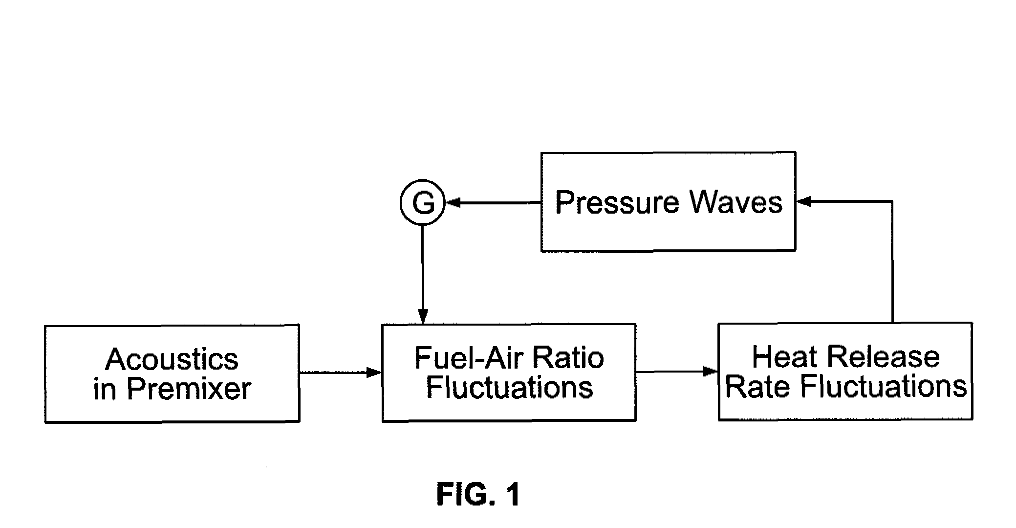
[0017]The process of thermoacoustic coupling is illustrated by the feedback loop depicted in FIG. 1. Inherent acoustic phenomenon occurring in a premixer cause fluctuations in the fuel-air ratio which, in turn, cause fluctuations in the heat release rate at the flame front. The heat release rate fluctuations are delayed with a time, τ, relative to the fuel-air ratio fluctuations. The time delay, τ, is given by L / U where L is the distance between the general point of fuel injection and the flame front. U is the m...


PUM


Abstract

An injection assembly for use with a combustor is provided. The injection assembly includes an effusion plate that has a plurality of plate openings and a plate sleeve having a sidewall portion that includes a forward edge. The forward edge is coupled to the effusion plate such that the effusion plate is oriented obliquely with respect to a centerline extending through the combustor. The injection assembly also includes a plurality of ring extensions where each of the ring extensions is coupled to one of the plurality of plate openings. Each ring extension extends rearwardly into the plate sleeve.

Description

BACKGROUND OF THE INVENTION[0001]This invention relates generally to gas turbine engines, and, more specifically, to lean premixed combustors used with gas turbines.[0002]Many known combustion turbine engines ignite a fuel-air mixture in a combustor and generate a combustion gas stream that is channeled to a turbine via a hot gas path. The turbine converts the thermal energy of the combustion gas stream to mechanical energy that rotates a turbine shaft. The output of the turbine may be used to power a machine, such as an electric generator or a pump.[0003]Environmental concerns regarding exhaust emissions generated from combustive processes have resulted in regulations and other limits on gas turbine engines. In response, at least some industrial gas turbine engines include a combustor designed for low exhaust emissions operation, for example, a lean-premixed combustor. Known lean-premixed combustors typically include a plurality of burner cans, or combustors, that circumferentially...

Claims


Application Information

Patent Timeline
IPC IPC(8): F02C1/00
CPCF23R3/286F23R2900/03041F23R2900/00014F02C7/22F02M63/00
Inventor HAN, FEIIYER, VENKATRAMAN ANANTHAKRISHMANMCMANUS, KEITH ROBERTSEVINCER, EDIP
Owner GENERAL ELECTRIC CO
Learn More