Eureka AIR delivers breakthrough ideas for toughest innovation challenges, trusted by R&D personnel around the world.

Processor Fault Isolation

a technology of fault isolation and processor, applied in the field of data processing, can solve problems such as the difficulty of detecting faults in a single processor, the failure of the board, and the failure of the system, and achieve the effect of avoiding the failure of the board

Active Publication Date: 2008-02-28
LENOVO GLOBAL TECH INT LTD
View PDF12 Cites 17 Cited by
  • Summary
  • Abstract
  • Description
  • Claims
  • Application Information

AI Technical Summary

Problems solved by technology

Since that time, computer systems have evolved into extremely complicated devices.
In such system, detecting faults in a single processor is a challenge.
If the trace is shorted to another signal or if the trace has been cut, the correct signal value will not show up at the destination pin, and the board will be known to have a fault.
As most of today's boards are very densely populated with components and tracks, it is very difficult for test systems to access the relevant areas of the board to enable them to test the board.
While his method is fine for code development, it poses challenges when using the processor's JTAG port for fault isolation purposes.
One problem is that if a single processor's fault is catastrophic enough to render its JTAG port inoperable, the chain is broken.
Another problem is that placing a processor in BYPASS mode typically is an operation effected out-of-band through a microcontroller, such as for example a Baseboard Management Controller (‘BMC’).
The BMC monitors the sensors and can send alerts to a system administrator via the network if any of the parameters do not stay within preset limits, indicating a potential failure of the system.
These abilities save on the total cost of ownership of a system.
The mechanics of putting a processor in BYPASS mode represents a large operational burden on such an embedded microcontroller.

Method used


Image

  • Processor Fault Isolation
  • Processor Fault Isolation
  • Processor Fault Isolation

Examples


Embodiment Construction

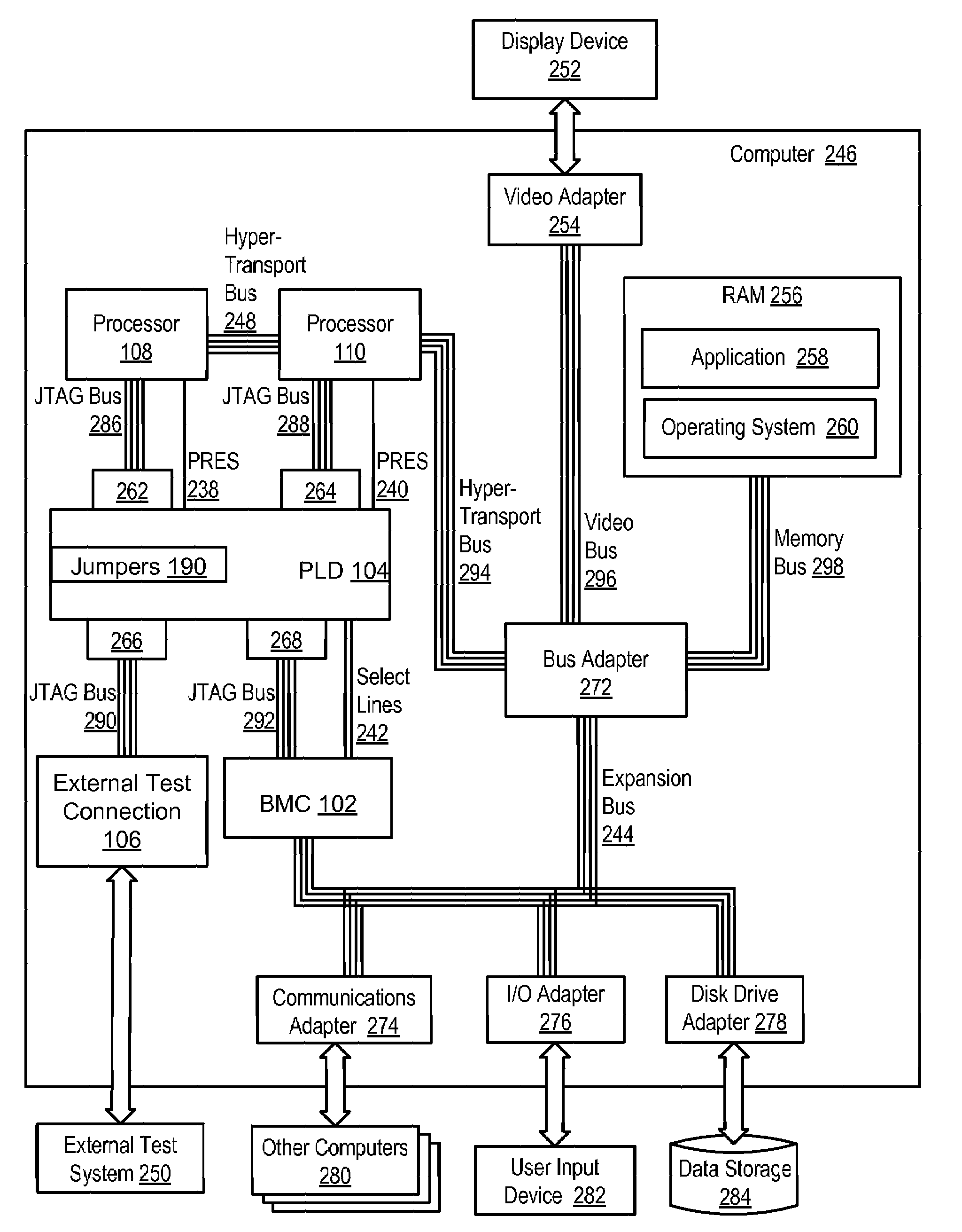
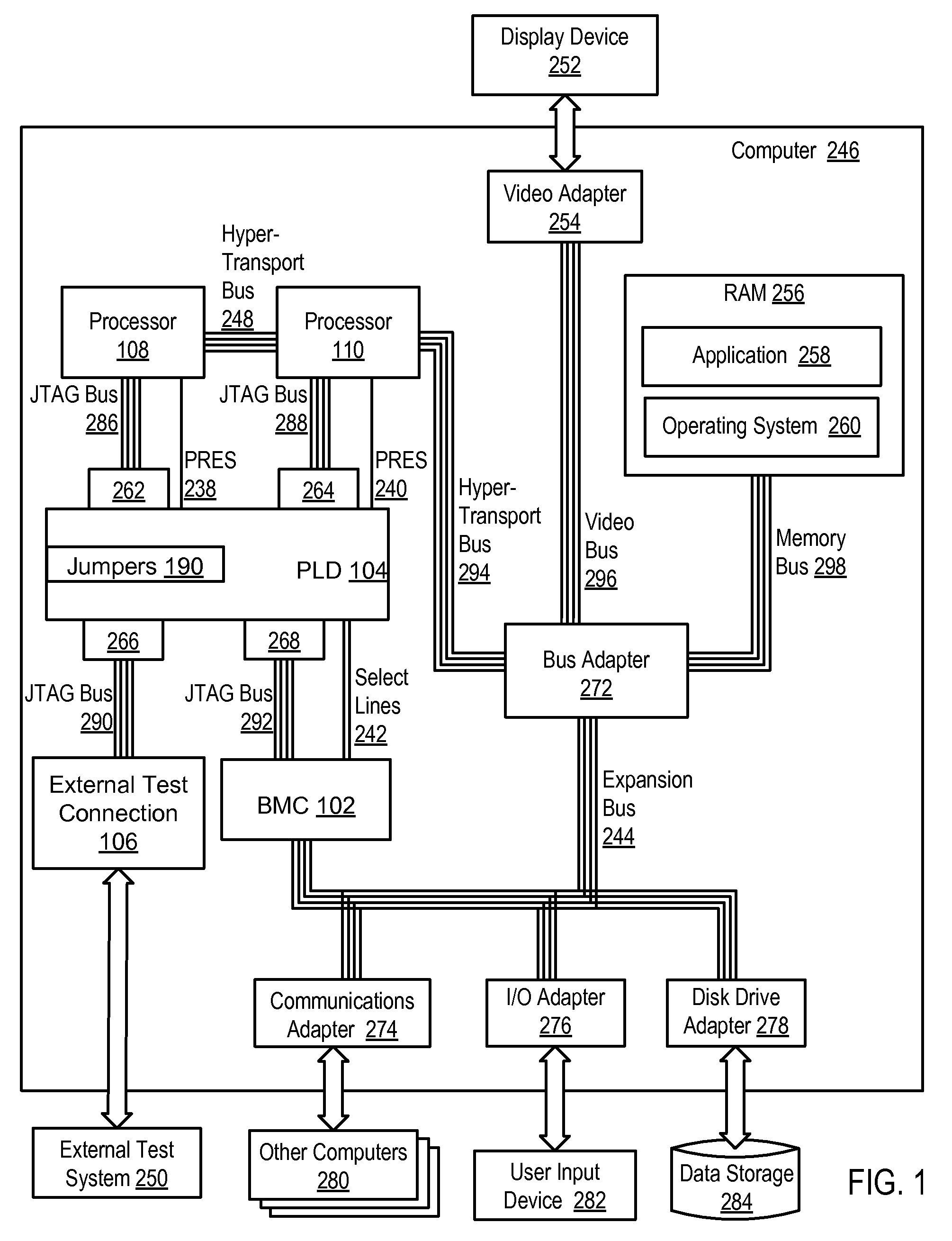
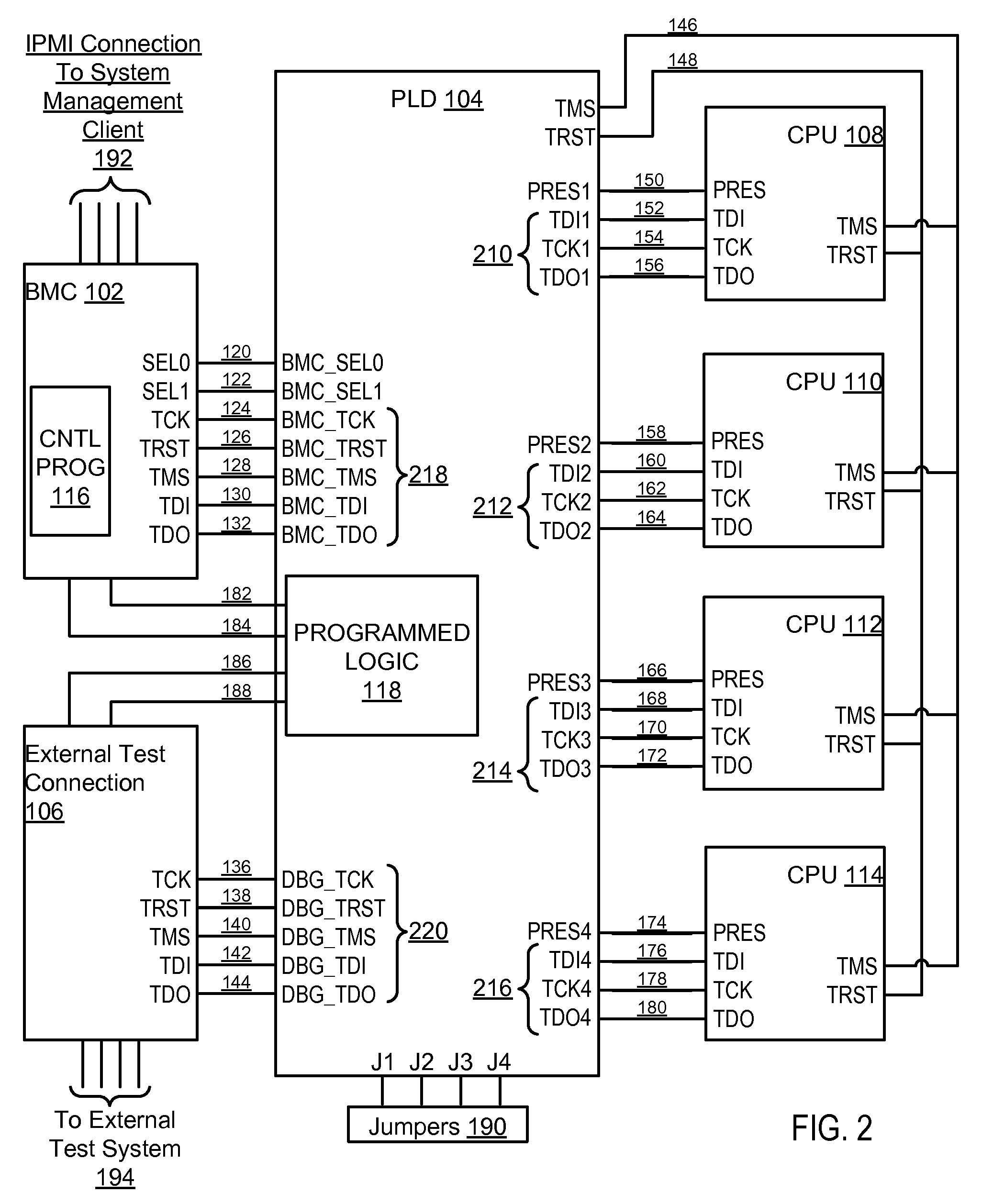
[0024]Exemplary methods, systems, and products for processor fault isolation according to embodiments of the present invention are described with reference to the accompanying drawings, beginning with FIG. 1. ‘Processor fault isolation,’ as the term is used in this specification, refers to determining the cause of a problem with a processor. The term includes methods that can isolate a source of a problem to a processor or to a component or logic circuit or even a particular register within a processor. Such methods can include boundary scan operations to isolate faults.

[0025]FIG. 1 sets forth a block diagram of an exemplary computer (246) useful for processor fault isolation according to embodiments of the present invention. The computer (246) of FIG. 1 includes two computer processors (108, 110) or ‘CPUs’ as well as random access memory (256) (‘RAM’) which is connected through a high speed memory bus (296) and bus adapter (272) to the processors (108, 110) and to other components ...


PUM


Abstract

Methods, apparatus, and products for processor fault isolation are disclosed that include sending, by an embedded system microcontroller to a programmable logic device (‘PLD’) a selection signal identifying one processor for boundary scan operations; sending boundary scan input signals to be sent to the identified processor; multiplexing by the PLD the boundary scan input signals to the identified processor; and sending boundary scan output signals returned from the identified processor. Methods, apparatus, and products for processor fault isolation are also disclosed that include connecting two or more processors in a boundary scan test chain, the connecting carried out by a PLD of a computer, the PLD further connected to sense lines carrying presence signals indicating whether processors are present in the computer; and including in the chain all processors indicated present according to presence signals.

Description

BACKGROUND OF THE INVENTION[0001]1. Field of the Invention[0002]The field of the invention is data processing, or, more specifically, methods, systems, and products for processor fault isolation.[0003]2. Description of Related Art[0004]The development of the EDVAC computer system of 1948 is often cited as the beginning of the computer era. Since that time, computer systems have evolved into extremely complicated devices. Today's computers are much more sophisticated than early systems such as the EDVAC. Computer systems typically include a combination of hardware and software components, application programs, operating systems, processors, buses, memory, input / output devices, and so on. As advances in semiconductor processing and computer architecture push the performance of the computer higher and higher, more sophisticated computer software has evolved to take advantage of the higher performance of the hardware, resulting in computer systems today that are much more powerful than ...

Claims


Application Information

Patent Timeline
Patent Type & Authority Applications(United States)
IPC IPC(8): G01R31/28
CPCG06F11/2242G01R31/318533
Inventor BRANDYBERRY, MARK A.WILSON, LEE H.
Owner LENOVO GLOBAL TECH INT LTD
Why Eureka
Eureka Blog
Learn More