
Thermochromic display assembly

a display and thermochromic technology, applied in the field of display assembly, can solve the problems of no image, dark and unappealing image, and display that is fully aesthetically appealing at both hot and cold states

Inactive Publication Date: 2008-02-28
INDICATORS
View PDF9 Cites 27 Cited by
  • Summary
  • Abstract
  • Description
  • Claims
  • Application Information

AI Technical Summary

Benefits of technology

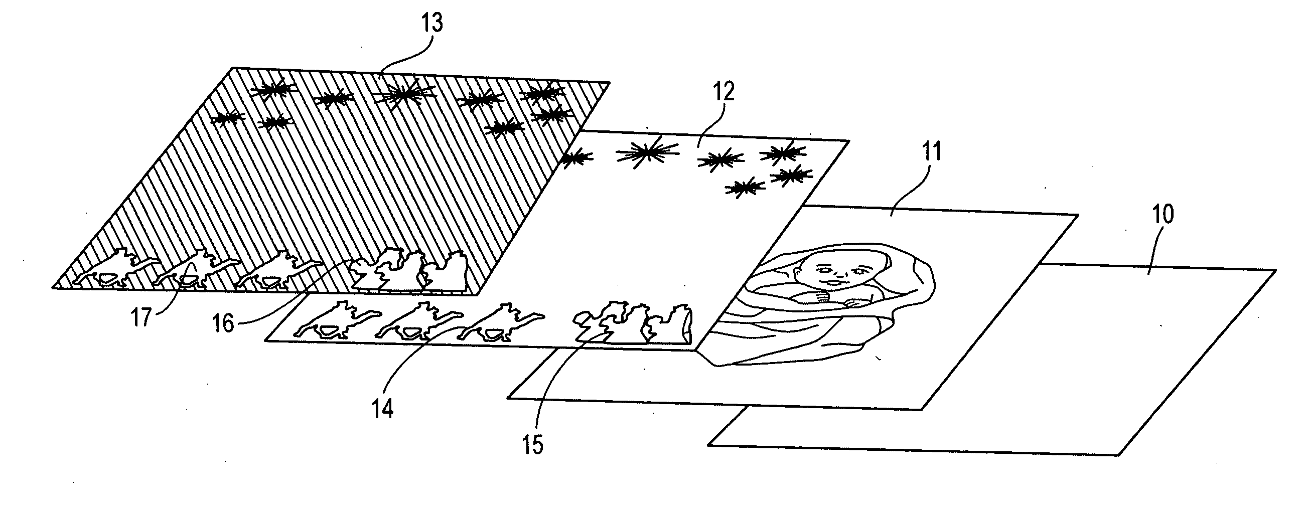
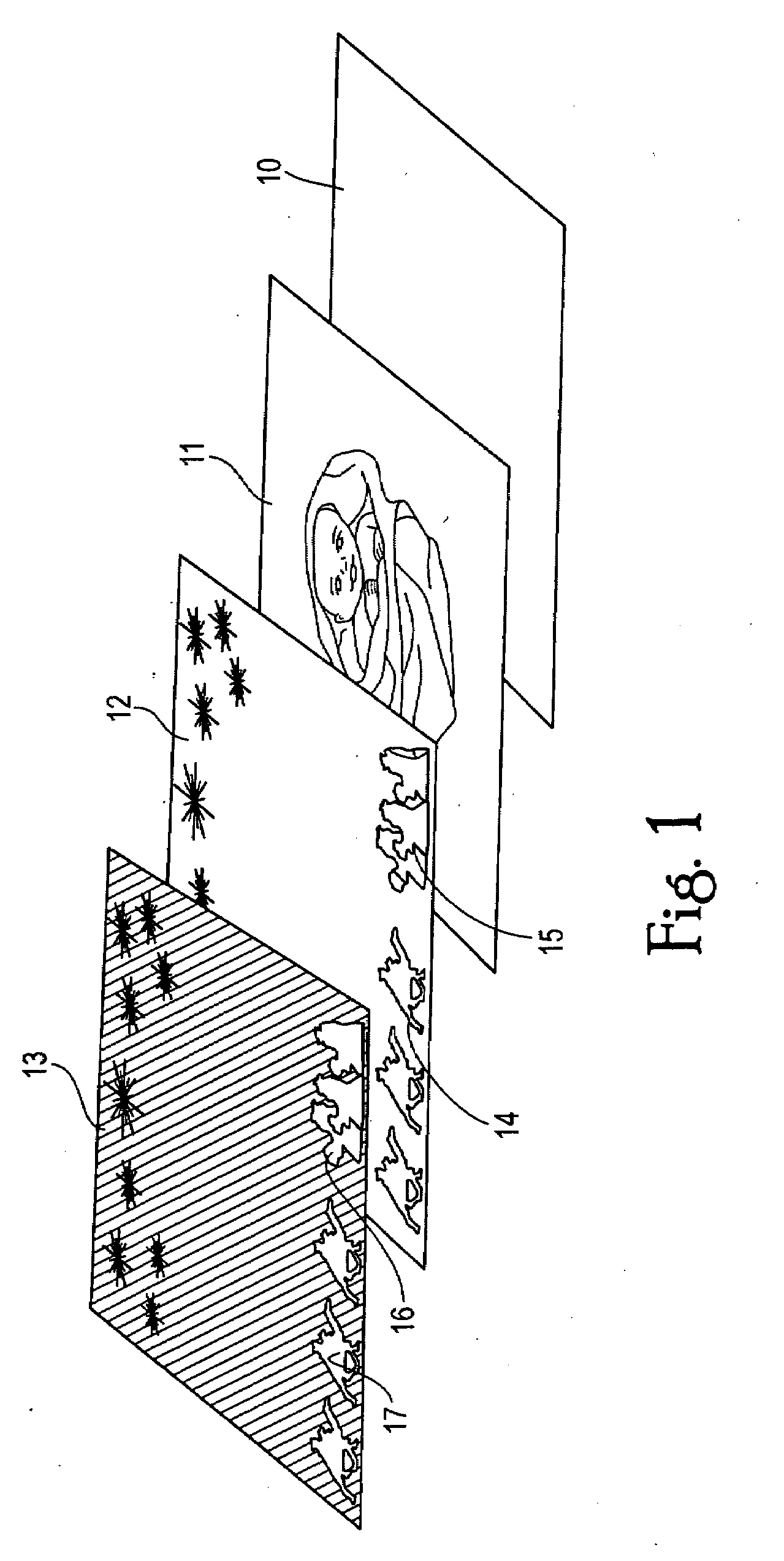
[0008]Thus, the first or bottom layer will have one or more colors either entirely covering the substrate or located in strategic places as desired (which may depend on where cut-out stencils or drop-out silkscreening are desired to be located, as described below). In addition, and preferred, a non-thermochromic color image is positioned onto the substrate. Preferably the one or more colors and / or the color image include two, three, four, or even more colors, as this significantly improves the aesthetic appeal of this layer. Four colors are preferred since this generally gives a pleasing image at a reasonable cost. However, as many colors as desired may be included.
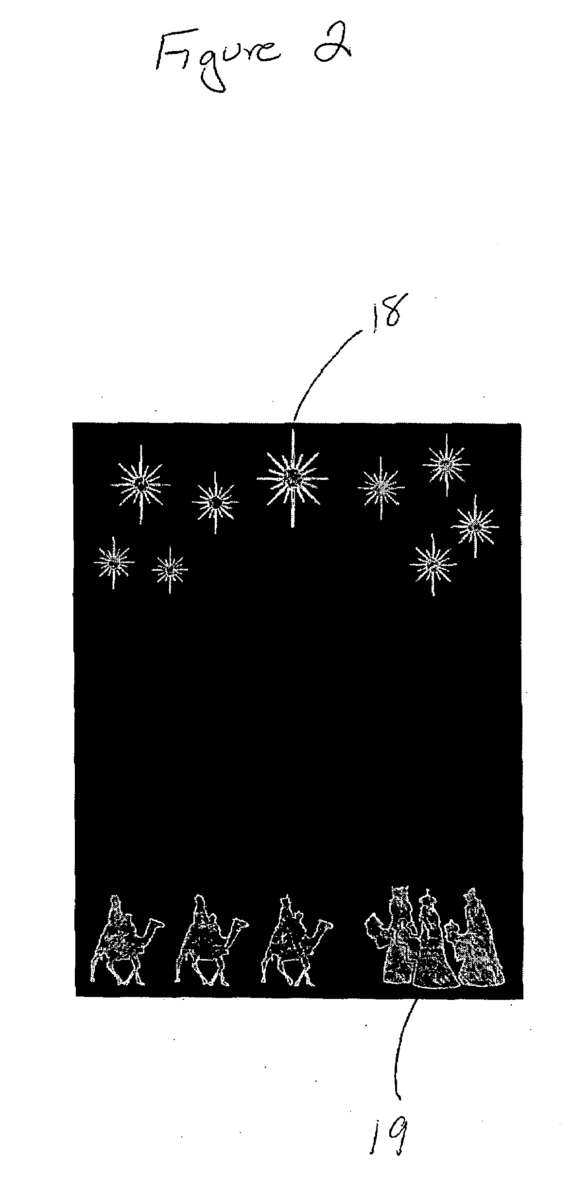
[0013]To maximize the aesthetic appeal, the one or more colors of the third layer are applied so as to make a desired image or picture. This is one of the advantages of this invention, that the third layer include an image that is visible at lower temperatures. To that end, it is preferable that the third layer include two, three, four or more colors. Four colors are preferred since this generally gives a pleasing image at a reasonable cost. However, as many colors as desired may be included. Preferably the colors include at least blue and red since these are popular colors and show up well against a dark-colored second layer.
[0024]In another related embodiment, there is contemplated a method of operating the above-described display assembly. The assembly is designed for easy and safe consumer use, especially when the end-use is a gift or novelty item. The basic method comprises the step of causing heat to be emitted from the heat source so as to heat the display region and consequently the display arrangement. This exposes the thermochromic inks of the second and third layers to sufficient heat so as to reach the color-changing temperature. As a result, the thermochromic inks become sufficiently transparent that (1) the color image made by the thermochromic inks of the third layer is not visible, (2) the cut-out stenciled images become no longer visible in their original configuration as cut-out images, and (3) and the non-thermochromic color image of the first layer becomes at least partially, and preferably fully, visible. There may be the additional step of cooling the heat source, which reverses the process, thereby allowing the display region to cool to lower temperature so that (1) the thermochromic inks of the second and third layers become again visible, (2) the cut-out stenciled images again become visible in their original configuration as cut-out images, and (3) the color image of the second layer is again masked from visibility.
[0029]A third step entails applying over the second layer thermochromic ink of at least one color (and in some embodiments, at least two colors) other than the color of the thermochromic ink of the second layer, such as described above, to form a third layer. Again, preferably the thermochromic ink is applied by well-known silkscreening techniques. The obscuring thermochromic ink of the second layer and the thermochromic ink(s) of the third layer are applied in such as way so that, in combination, they are sufficient to mask from visibility at lower temperature the color image of the first layer.

Problems solved by technology

However, displays that are fully aesthetically appealing at both hot and cold states are not well known.
Currently known display items using thermochromic inks generally have colorful images at elevated temperatures, but at cold or ambient temperature are limited to a dark and unappealing image, or no image at all.

Method used


Image

  • Thermochromic display assembly
  • Thermochromic display assembly
  • Thermochromic display assembly

Examples


Embodiment Construction

[0050]We have described display arrangements that change appearance upon changes in temperature. Our display arrangements uniquely combine both thermochromic and non-thermochromic inks that visualize colors, patterns and images at lower temperatures, and at higher temperatures show a different set of colors, patterns and images as the thermochromic inks change color or become transparent—thus, the images vary at cold state and hot state temperatures. These display arrangements and display assemblies are visually pleasing at all temperatures, simple to use, and interesting to observe change appearance.

[0051]The term “display arrangement” is used in connection with our invention to denote a layered composite structure or article which conveys a visual design, message or graphics image, including any sort of a pattern or picture. As is apparent from the examples and our description, there is a broad range of possible visual designs and effects that can be displayed, both in the cold st...


PUM

PropertyMeasurementUnit
temperatureaaaaaaaaaa
temperature T2aaaaaaaaaa

Abstract

This invention encompasses display arrangements and assemblies having multiple layers. The base layer has a color image of non-thermochromic ink, a second layer includes a thermochromic ink, and a third layer includes a thermochromic ink forming an image visible on top of the second layer. The second and third layers largely mask the non-thermochromic ink from view. Cut-out stenciled images are cut through the second and third layer so that the non-thermochromic colors of the base layer are visible through them. At a lower temperature, the thermochromic inks are visible as well as the non-thermochromic ink colors through the cut-out stenciled image areas. At a higher, color-changing temperature, the thermochromic inks become sufficiently transparent that the non-thermochromic colors of the base layer are visible.

Description

FIELD OF THE INVENTION[0001]This invention relates to a display assembly having a unique ornamentation effect. The display arrangement makes use of both thermochromic and non-thermochromic colors to display reversible color images that are different at different temperatures.BACKGROUND OF THE INVENTION[0002]The novelty and collectibles market thrives on innovation, fun and cutting edge aesthetic designs. Decorative display items are consistently in demand as gift items, decor, collectibles, seasonal and religious merchandise and the like.[0003]Consumer product display items including thermochromic or thermally color-changing inks are known. However, displays that are fully aesthetically appealing at both hot and cold states are not well known. Currently known display items using thermochromic inks generally have colorful images at elevated temperatures, but at cold or ambient temperature are limited to a dark and unappealing image, or no image at all.SUMMARY OF THE INVENTION[0004]Th...

Claims


Application Information

Patent Timeline
Patent Type & Authority Applications(United States)
IPC IPC(8): B32B3/10B44C5/00B41M5/00B05D1/32B05D1/36
CPCY10T428/24802B44F1/06
Inventor CHRISTOFER, PETERSCHLESSINGER, BRIAN
Owner INDICATORS
Learn More