
Submarine optical transmission systems having optical amplifiers of unitary design

a technology of optical amplifier and unitary design, applied in the direction of transmission, electromagnetic transmission, electric apparatus, etc., can solve the problems of complex and time-consuming design, testing and deployment, and less desirable network landing points of repeater-less networks, and achieve high engineering costs, highly desirable services and capabilities, and high economics.

Inactive Publication Date: 2008-02-28
HUAWEI MARINE NETWORKS CO LTD
View PDF24 Cites 5 Cited by
  • Summary
  • Abstract
  • Description
  • Claims
  • Application Information

AI Technical Summary

Benefits of technology

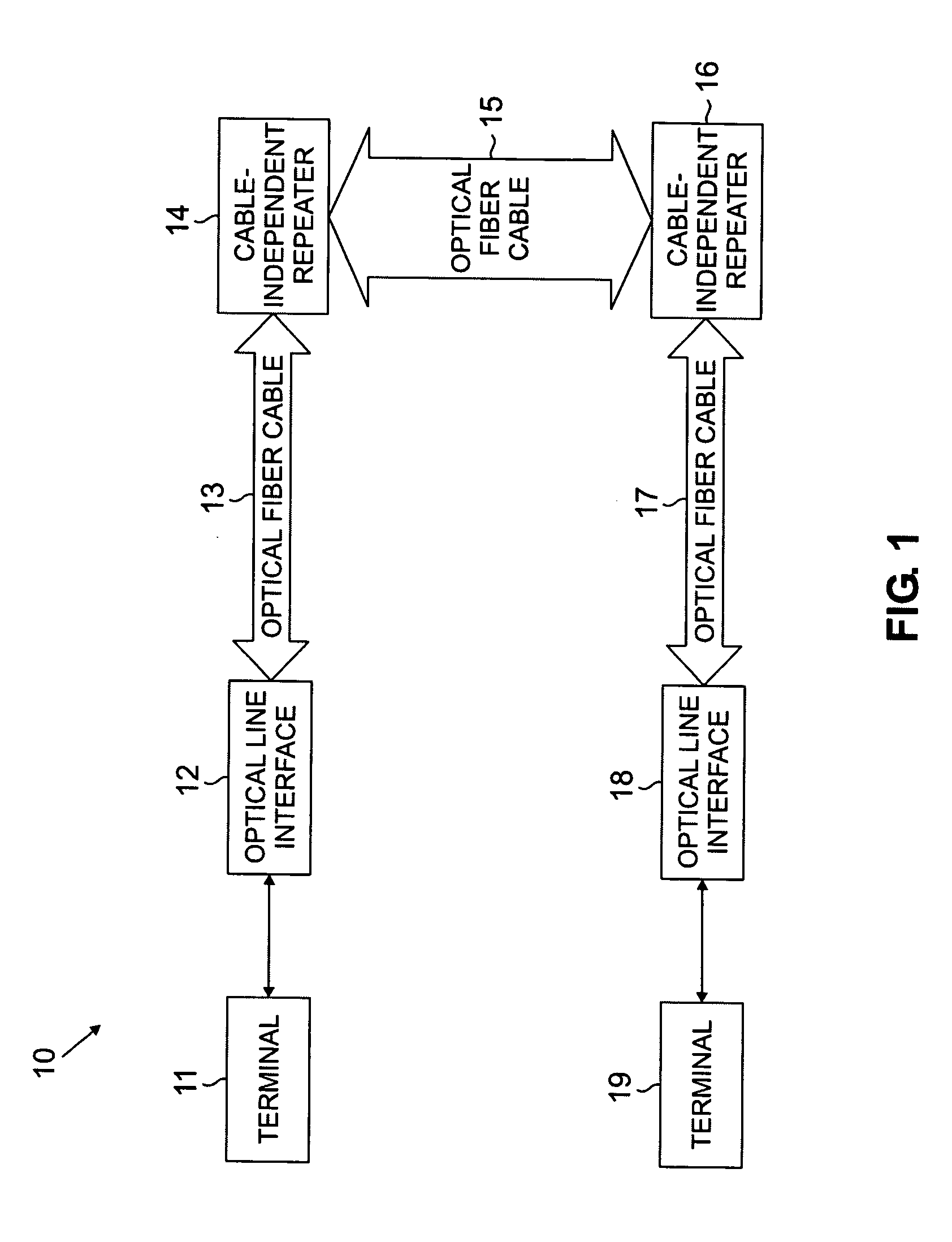
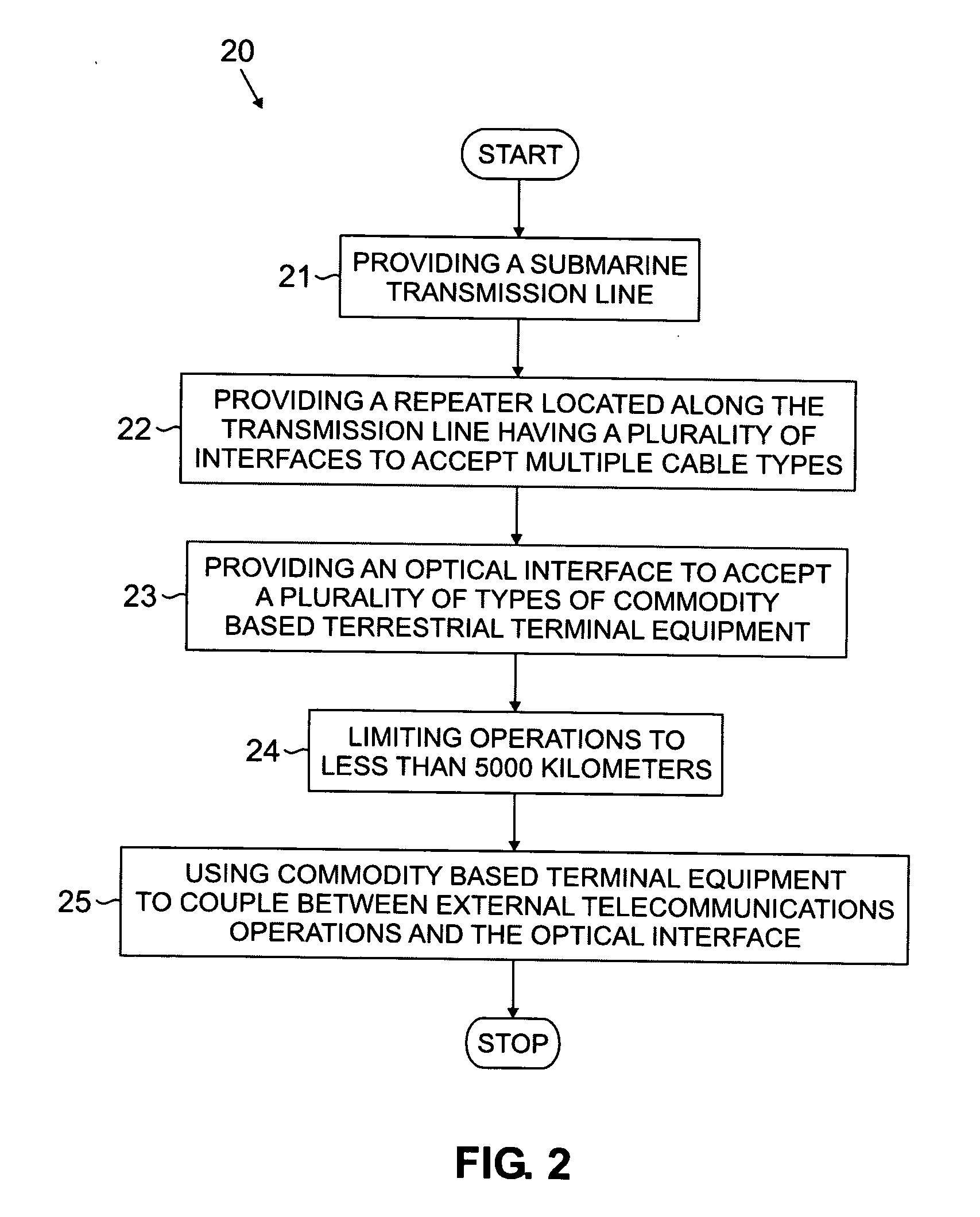
[0010]For example, one exemplary embodiment of the present invention employs a optical repeater that can be used with a wide variety of different existing submarine cables, in combination with an optical line interface terminal that can accept existing terrestrial terminal devices. Regarding market division, this embodiment is specifically limited to spans of less than about 4000 kilometers, thereby straddling and overlapping with both the long-haul and short-haul markets while providing highly desirable services and capability. By selecting this market segment, the embodiment achieves highly desirable economics without the usual concomitant high engineering costs.

Problems solved by technology

A maximum upper limit of 400-450 km is observed in practice because the line loss, which scales with distance, outstrips available line gain, the ability to launch more power into the line, and the ability of the system to resolve the received optical signal.
As a result, repeater-less networks often are forced to incorporate less desirable network landing points, from political or economic standpoints, because of the inherent distance limitation imposed by the underlying non-amplified technology.
While the technology used is highly capable, it is also complex and time-consuming to design, test and deploy.
Initial capital costs in long-haul systems tend to be very high, although per-bit transport costs are often attractive if the systems are built-out to maximum design capacity through Dense Wavelength Division Multiplexing (DWDM) technology where many data streams at varying wavelengths are simultaneously carried on the same line.
Long-haul technology generally is not economically scalable downwards to systems having shorter length and capacity requirements.
As bandwidth demand is less on shorter regional routes compared with the big transoceanic “pipes,” high design capacity is not available to drive the favorable economics associated with the long-haul technology.
And, as long-haul technology is expressly designed to meet the long-distance and large bandwidth capacity demanded in the sector, it is simply not possible from feature set and engineering viewpoints to decontent a long-haul platform to meet the more modest requirements of the regional market.
For any new business trying to enter either of these markets, there are significant barriers to entry, including but not limited to high capital investment, long time to market, and large equipment purchases for inventory, which can be obsolete technology in a short period of time.

Method used


Image

  • Submarine optical transmission systems having optical amplifiers of unitary design
  • Submarine optical transmission systems having optical amplifiers of unitary design
  • Submarine optical transmission systems having optical amplifiers of unitary design

Examples


Embodiment Construction

[0020]It is worthy to note that any reference herein to “one embodiment” or “an embodiment” means that a particular feature, structure, or characteristic described in connection with the embodiment is included in at least one embodiment of the invention. The appearances of the phrase “in one embodiment” in various places in the specification are not necessarily all referring to the same embodiment.

[0021]According to one aspect of the present invention, existing Wavelength Division Multiplexed (“WDM”) terrestrial and undersea technologies are merged into a feature-rich, yet low-cost platform that is purpose-built for the regional undersea market—a market that is significant, robust, and totally underserved by incumbent undersea suppliers.

[0022]Embodiments of the present invention are designed for undersea networks having maximum link distances of about 5,000 kilometers. Within this sector, the business model tracks extremely well to significant opportunities in the range of 350 to 4,...


PUM


Abstract

A method for entering a market with high barriers to entry and a plurality of proprietary business elements includes converting at least one of the business elements into a universal business element that can accept a wide variety of inputs from other business elements, while converting a remaining one of the plurality of business elements to commoditized business elements. In addition, a market of a resulting business is limited so that the resulting business straddles a gap between two subdivisions of the market. Thus, a combination of technology and market division enables conversion of otherwise proprietary system to commodity equipment that can work with a wide variety of existing vendor equipment while competing technologically with highly engineered solutions. For example as applied to the undersea telecommunications market, one exemplary embodiment of the present invention employs an optical repeater that can accept any existing submarine cable, in combination with an optical line interface terminal that can accept existing terrestrial terminal equipment. Regarding market division, this embodiment is specifically limited to spans of less than 5000 kilometers, and preferably between 350 and 4000 kilometers, thereby straddling both the long-haul and short-haul markets while providing highly desirable services and capability. By selecting this market segment, the embodiment achieves highly desirable economics without the usual concomitant high engineering costs.

Description

RELATED APPLICATIONS[0001]The present invention is related to co-pending and commonly assigned U.S. patent application Ser. No. 10 / 739,929, filed Dec. 18, 2003 and entitled “Method for Commoditizing Elements of Previously Specialized Communications Links,” which is incorporated by reference in its entirety herein.FIELD OF THE INVENTION[0002]The present invention is directed generally to methods for converting vertically integrated communications business processes into horizontally integrated communications businesses, and more particularly to a method for converting a vertically integrated communications business into a horizontally integrated communications business that enables new business opportunities for a single entity.BACKGROUND[0003]The undersea optical telecommunications market comprises an exemplary vertically integrated business. This market is segmented into short-haul and long-haul operations. Short-haul, or repeater-less systems employ links without powered in-line a...

Claims


Application Information

Patent Timeline
IPC IPC(8): H04B10/00
CPCH04B10/2935
Inventor EVANGELIDES, STEPHEN G.MORREALE, JAY P.NEUBELT, MICHAEL J.YOUNG, MARK K.NAGEL, JONATHAN A.DEVINCENTIS, DAVID S.
Owner HUAWEI MARINE NETWORKS CO LTD
Learn More