
Laser display apparatus

a technology of laser display and display apparatus, which is applied in the direction of polarising elements, instruments, television systems, etc., can solve the problems of image quality degradation of the display apparatus, difficult to use a semiconductor laser as the light source in the display apparatus, and speckle noise, etc., to reduce speckle patterns, reduce optical efficiency, and simple optical structure

Inactive Publication Date: 2008-02-28
SAMSUNG ELECTRONICS CO LTD
View PDF3 Cites 23 Cited by
  • Summary
  • Abstract
  • Description
  • Claims
  • Application Information

AI Technical Summary

Benefits of technology

[0009]An apparatus consistent with the present invention reduces speckle patterns using a simple optical structure that does not reduce an optical efficiency.

Problems solved by technology

However, due to speckle noises generated by high coherence of the laser, it is difficult to use a semiconductor laser as the light source in a display apparatus.
The speckle noise occurs when coherent beams having arranged phases are scattered on a screen, that is, an arbitrary phase surface, and wave fronts that are scattered on adjacent portions on the screen interfere with each other on a retina, that is, an observing surface.
The speckle noise is manifested as uneven light intensity distribution on the observing surface, and consequently, causes an image quality degradation of the display apparatus.
However, the above method using the active device has some problems.
However, according to this method, the optical path difference must be large enough to remove the coherence between the separated two laser beams, and thus, the display apparatus must have a large size.

Method used


Image

  • Laser display apparatus
  • Laser display apparatus
  • Laser display apparatus

Examples


Embodiment Construction

[0028]The present invention will now be described more fully with reference to the accompanying drawings, in which exemplary embodiments of the invention are shown.

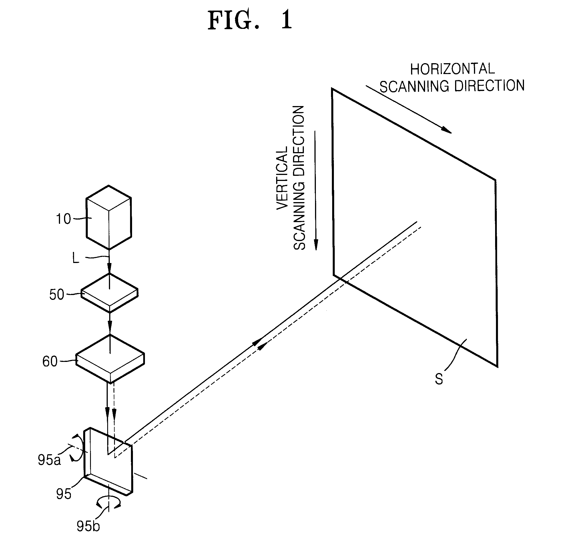
[0029]FIG. 1 is a schematic view of a laser display apparatus according to an embodiment of the present invention.

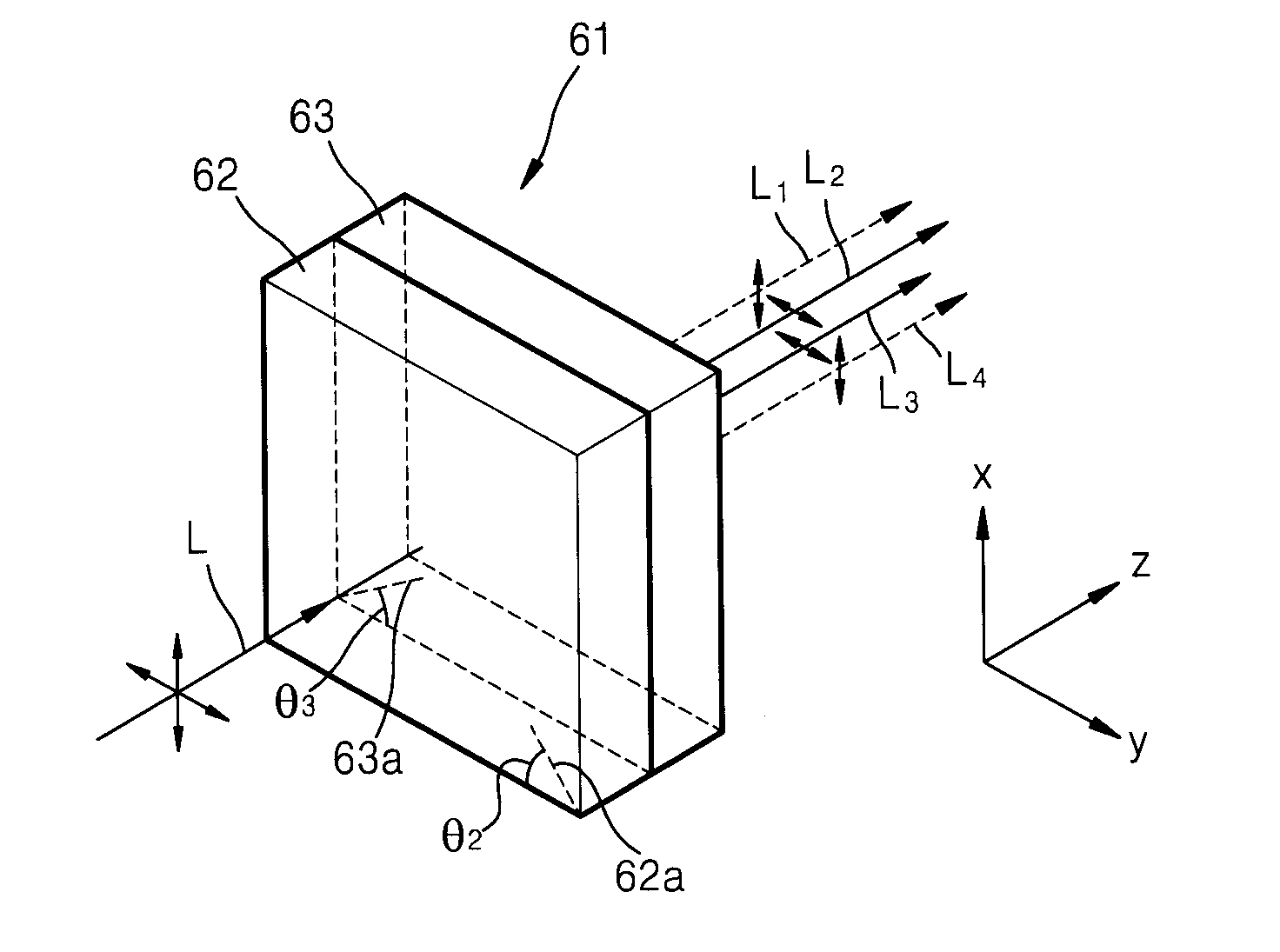
[0030]Referring to FIG. 1, the laser display apparatus of the current embodiment includes a laser illuminating system 10 emitting laser beam L, a speckle reducing unit separating the laser beam L emitted from the laser illuminating system 10 into two partial beams (not written on FIG. 1) L1 and L2, a dual-axis driving micro scanner 95 scanning the partial beams L1 and L2, and a screen S on which an image is formed. The speckle reducing unit includes a quarter wave plate 50 and a birefringent device 60. Two spots formed on the screen S by the partial beams L1 and L2 separated by the speckle reducing unit overlap with each other, and form a pixel.

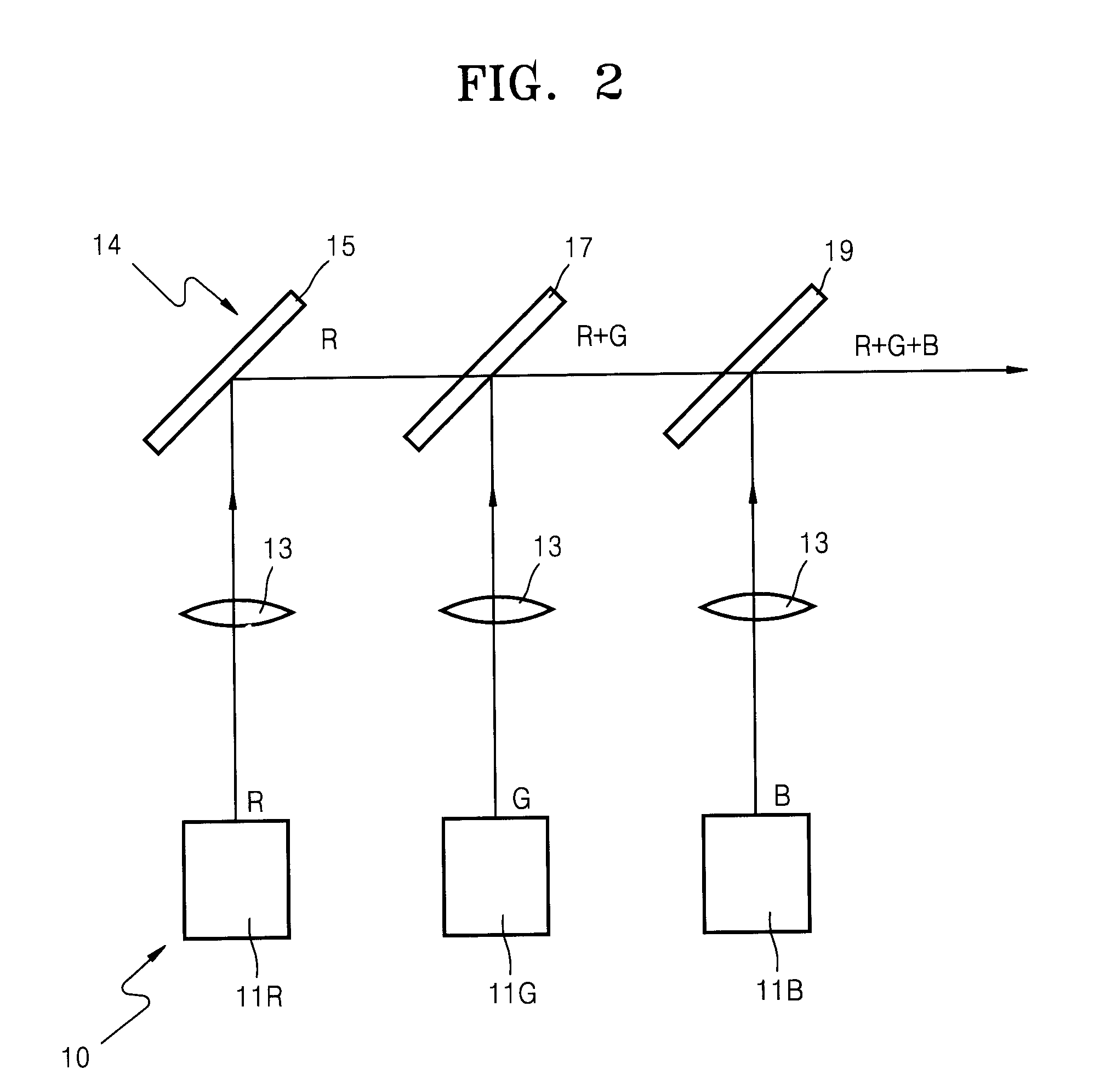
[0031]The laser illuminating system 10, for example, includes a re...


PUM


Abstract

A laser display apparatus which reduces speckles, includes: a laser illuminating system emitting a laser beam; and a speckle reducing unit including a birefringent device that separates the laser beam emitted from the laser illuminating system into a plurality of partial beams, and a plurality of spots formed by the partial beams, separated by the speckle reducing unit, on a screen overlap with each other with a slight displacement so that the speckle pattern is reduced.

Description

CROSS-REFERENCE TO RELATED PATENT APPLICATIONS[0001]This application claims the benefit of Korean Patent Application No. 10-2006-0081839, filed on Aug. 28, 2006, in the Korean Intellectual Property Office, the disclosure of which is incorporated herein in its entirety by reference.BACKGROUND OF THE INVENTION[0002]1. Field of the Invention[0003]The present invention relates to a laser display apparatus, and more particularly, to a laser display apparatus reducing a speckle pattern caused by coherence of a laser light source.[0004]2. Description of the Related Art[0005]Semiconductor lasers have high photoelectron conversion efficiency and high directionality, and thus, are suitable as a light source in a display apparatus. However, due to speckle noises generated by high coherence of the laser, it is difficult to use a semiconductor laser as the light source in a display apparatus. The speckle noise occurs when coherent beams having arranged phases are scattered on a screen, that is, ...

Claims


Application Information

Patent Timeline
IPC IPC(8): G02B26/08G02B27/28
CPCG02B5/3083G02B26/101G02B27/104G02B27/12G02B19/0028G02B27/283G02B27/48G02B19/0057G02B27/145H04N5/74G09G3/02G02B26/10
Inventor PARK, KI-SOOBORODOULINE, ALEXEIMOON, JOON-SEOK
Owner SAMSUNG ELECTRONICS CO LTD
Learn More