
Multi-column type electron beam exposure apparatus

Inactive Publication Date: 2008-02-28
ADVANTEST CORP
View PDF7 Cites 10 Cited by
  • Summary
  • Abstract
  • Description
  • Claims
  • Application Information

AI Technical Summary

Benefits of technology

[0013] The present invention has been made in consideration for the foregoing problems inherent in the prior art. It is an object of the present invention to provide a multi-column type electron beam exposure apparatus capable of eliminating movements of electron beam to be exposed in column cells, thus transmitting exposure data to columns with accuracy, and thereby achieving high-precision exposure.
[0015] According to the present invention, the exposure data undergoes 8B10B encoding and thereby conversion into the serial data, which in turn is converted into the light signal and is transmitted. This reduces the number of cables for use in exposure data transmission. For example, the required number of cables is reduced from 36 to 1. The use of a small number of cables enables preventing a phenomenon in which vibrations from the cables cause vibrations of the columns and hence movements of the electron beam.
[0017] According to the present invention, the code for transmission error detection and correction (e.g., ECC) is calculated based on the exposure data, thereby enabling correction of a single-bit transmission error. Further, a mechanism is provided to detect whether or not the code for error detection and correction in itself is transmitted correctly, thereby ensuring that the exposure data is transmitted. This prevents transmission of erroneous exposure data and hence an erroneous exposure process, thereby preventing a reduction in throughput.
[0019] According to the present invention, the signal having the period longer than the transmission delay time developing between the exposure data transmitting unit and the exposure data receiving unit is used to transmit the encoded exposure data and read out the received data. This makes it possible to absorb a varying transmission delay time which is contained in the transmission delay time, and which develops as varying from one encoding to another. Accordingly, the column cells securely receive the exposure data, and this makes it possible to emit electron beam at a predetermined spot.

Problems solved by technology

The electron beam exposure apparatus has the feature of having good resolution but has the problem of having low exposure throughput, as compared to a photolithography apparatus.
However, the multi-column type electron beam exposure apparatus has problems as given below.
Because of this, the twisted pair cables increase in weight and vibrations propagate from the cables to the columns.
This vibration of columns may lead to position variation of electron beam to be exposed.
However, this leads to an increase in a transmission load on an analog amplifier and hence to a reduction in the exposure throughput.

Method used


Image

  • Multi-column type electron beam exposure apparatus
  • Multi-column type electron beam exposure apparatus
  • Multi-column type electron beam exposure apparatus

Examples


Embodiment Construction

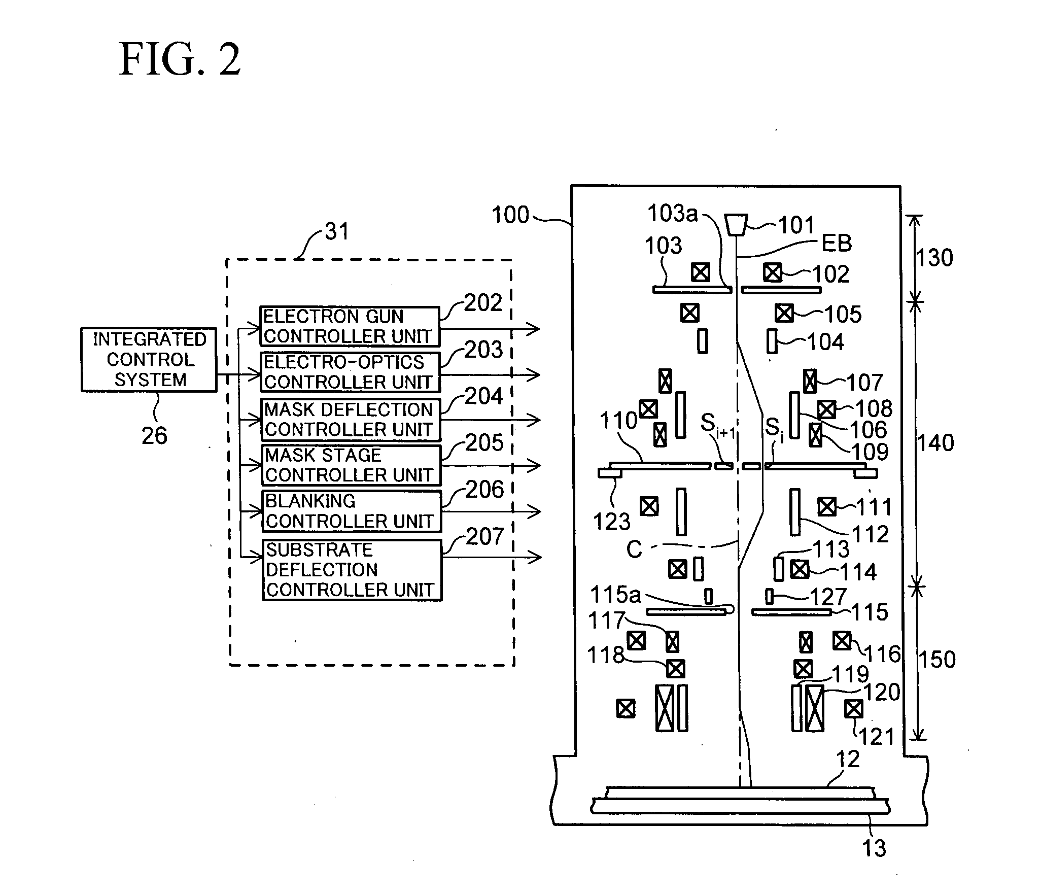
[0029] An embodiment of the present invention will be described below with reference to the accompanying drawings.

[0030] Firstly, description will be given with regard to the configuration of a multi-column type electron beam exposure apparatus. Secondly, description will be given with regard to the configuration and operation of an exposure data transmitter unit that transmits exposure data from a correction computing unit to a column cell unit. Thirdly, description will be given with regard to the configuration of an optical transmission frame containing transmitted exposure data as a constituent. Finally, description will be given with regard to a fixed delay in transmission.

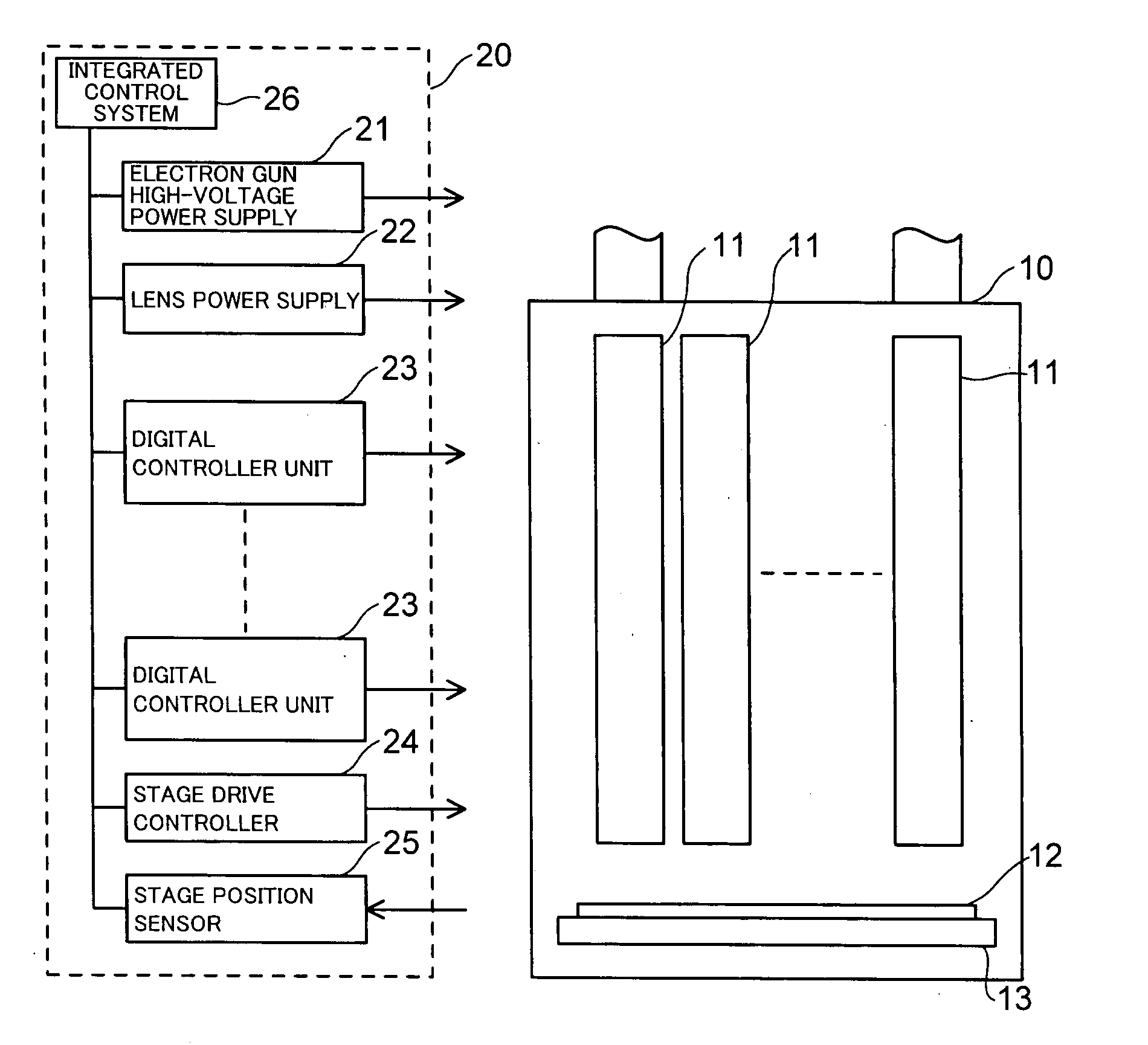
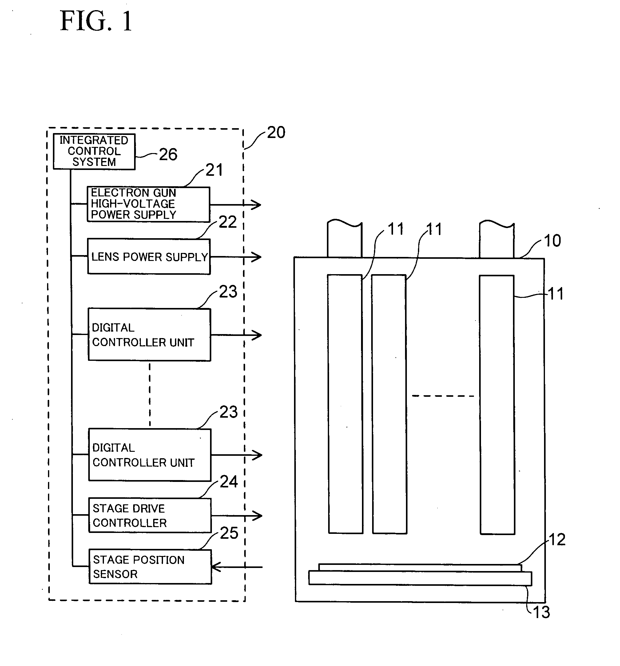
[0031]FIG. 1 is a schematic illustration of the configuration of a multi-column type electron beam exposure apparatus according to the embodiment of the present invention. The multi-column type electron beam exposure apparatus is broadly divided into an electron beam column 10 and a controller unit 20 that ...


PUM


Abstract

A multi-column type electron beam exposure apparatus includes: plural column cells disposed over a wafer, each including an electron gun, deflector for deflecting an electron beam emitted by the electron gun, and exposure data receiving unit for receiving exposure data; and correction computing unit for calculating the exposure data for use in the column cells. The correction computing unit includes exposure data controlling unit and exposure data transmitting unit for each of the column cells. The exposure data transmitting unit encodes the exposure data corrected by the exposure data controlling unit to convert the data into serial data, converts the serial data into a light signal, and transmits the light signal. The exposure data receiving unit converts the light signal into an electric signal, and decodes the encoded exposure data to convert the data into parallel data.

Description

CROSS-REFERENCE TO RELATED APPLICATIONS [0001] This is a continuation of International Patent Application No. PCT / JP2006 / 306271, filed Mar. 28, 2006, which is herein incorporated by reference.BACKGROUND OF THE INVENTION [0002] 1. Field of the Invention [0003] The present invention relates to an electron beam exposure apparatus, and more particularly to a multi-column type electron beam exposure apparatus including plural columns which are disposed over a wafer, and which concurrently perform an exposure process. [0004] 2. Description of the Prior Art [0005] Recently, an electron beam exposure apparatus has come into use for fine patterning in a lithography process for manufacture of a semiconductor device or the like. [0006] The electron beam exposure apparatus has the feature of having good resolution but has the problem of having low exposure throughput, as compared to a photolithography apparatus. As opposed to the above apparatus, a multi-column type electron beam exposure appar...

Claims


Application Information

Patent Timeline
IPC IPC(8): G03B27/42
CPCB82Y10/00B82Y40/00H01J2237/31774H01J2237/31762H01J37/3177
Inventor YABARA, HIDEFUMIMIYAZAWA, KENICHISAKAZAKI, TOMOHIROTANAKA, KAZUAKI
Owner ADVANTEST CORP
Learn More