
Wireless key and door remote control system

Active Publication Date: 2008-02-28
DENSO CORP
View PDF6 Cites 35 Cited by
  • Summary
  • Abstract
  • Description
  • Claims
  • Application Information

AI Technical Summary

Benefits of technology

[0009] The present invention has therefore an object to provide a wireless key that is capable of preventing an unnecessary reception standby state and also is capable of effectively utilizing the lifetime of a built-in battery, and a door remote locking and unlocking control system having the wireless key.

Problems solved by technology

A power supply of the receiver circuit is normally provided by a built-in dry battery, and hence the built-in battery is liable to run down easily because of always holding the reception standby state.
However, because the reception standby state continues in that state, there is the possibility that a battery lifetime of the wireless key ends unexpectedly early after the vehicle has been delivered to the user, and the wireless key cannot be used.
Also, when the receiver circuit malfunctions due to a noise of an electric appliance, the battery consumption is further accelerated because the power consumption at the time of the reception is large.
Also, malfunction occurs due to noises.
The power consumption of the wireless key that is used by a normal user is larger at the time of getting on or off the vehicle because of a polling response.
However, a period of time required for the polling response communication at the time of getting on or off the vehicle and the number of times of the polling response communication per day are limited.
As a result, most of the battery power is consumed in the reception standby state in the case of the constantly used wireless key.
Accordingly, when the constantly used wireless key and the spare key are delivered to the user at the same time, there are many cases in which the battery power of the spare wireless key is naturally nearly exhausted when the battery lifetime of the constantly used wireless key is ended.
Since the self-discharge of the dry battery is liable to be influenced by the storage temperature, the battery lifetime of the spare wireless key might have been already exhausted depending on the storage state.
As a result, when the battery of the constantly used wireless key is exhausted and cannot be used, the battery of the spare wireless key is also exhausted with the result that a role as “spare” is not exerted.
The similar problem will also arise if a similar wireless key is applied to a door remote locking and unlocking control system for various subject bodies such as houses and buildings.

Method used


Image

  • Wireless key and door remote control system
  • Wireless key and door remote control system
  • Wireless key and door remote control system

Examples


Embodiment Construction

[0022] The present invention will be described in detail with reference to an embodiment, which is directed to a door remote locking and unlocking control system for a vehicle, which is one example of a subject body to be controlled.

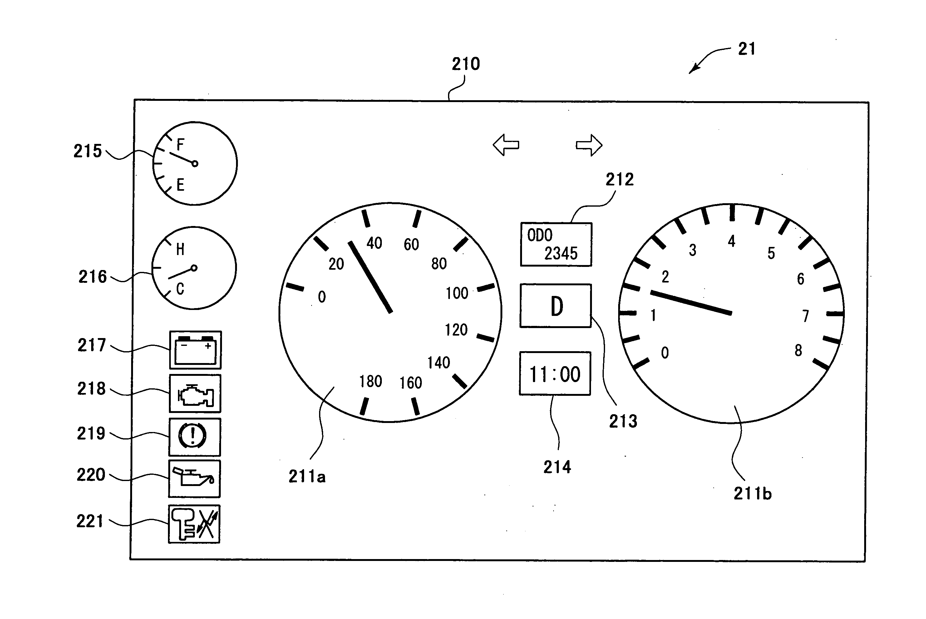
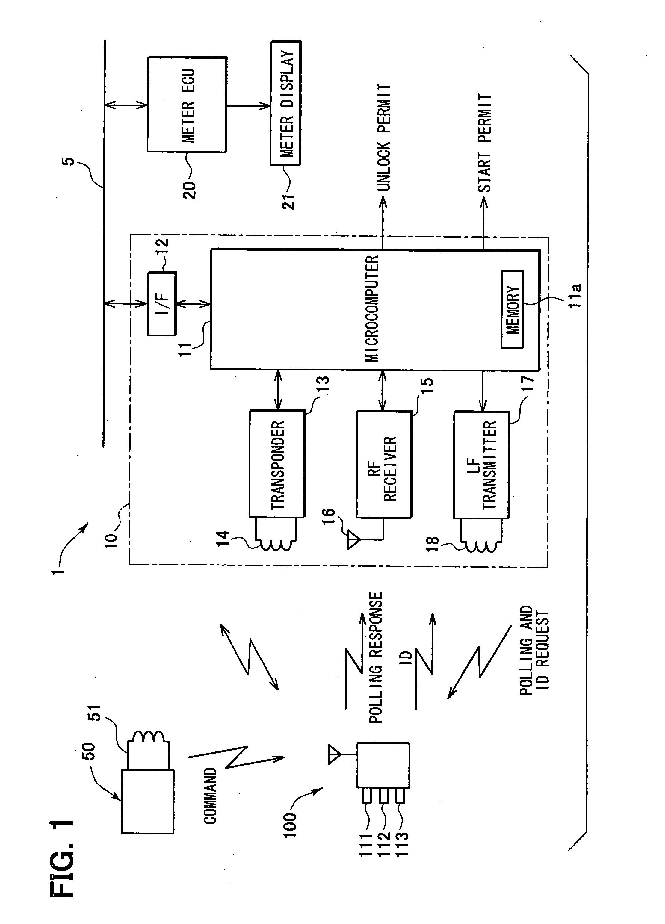
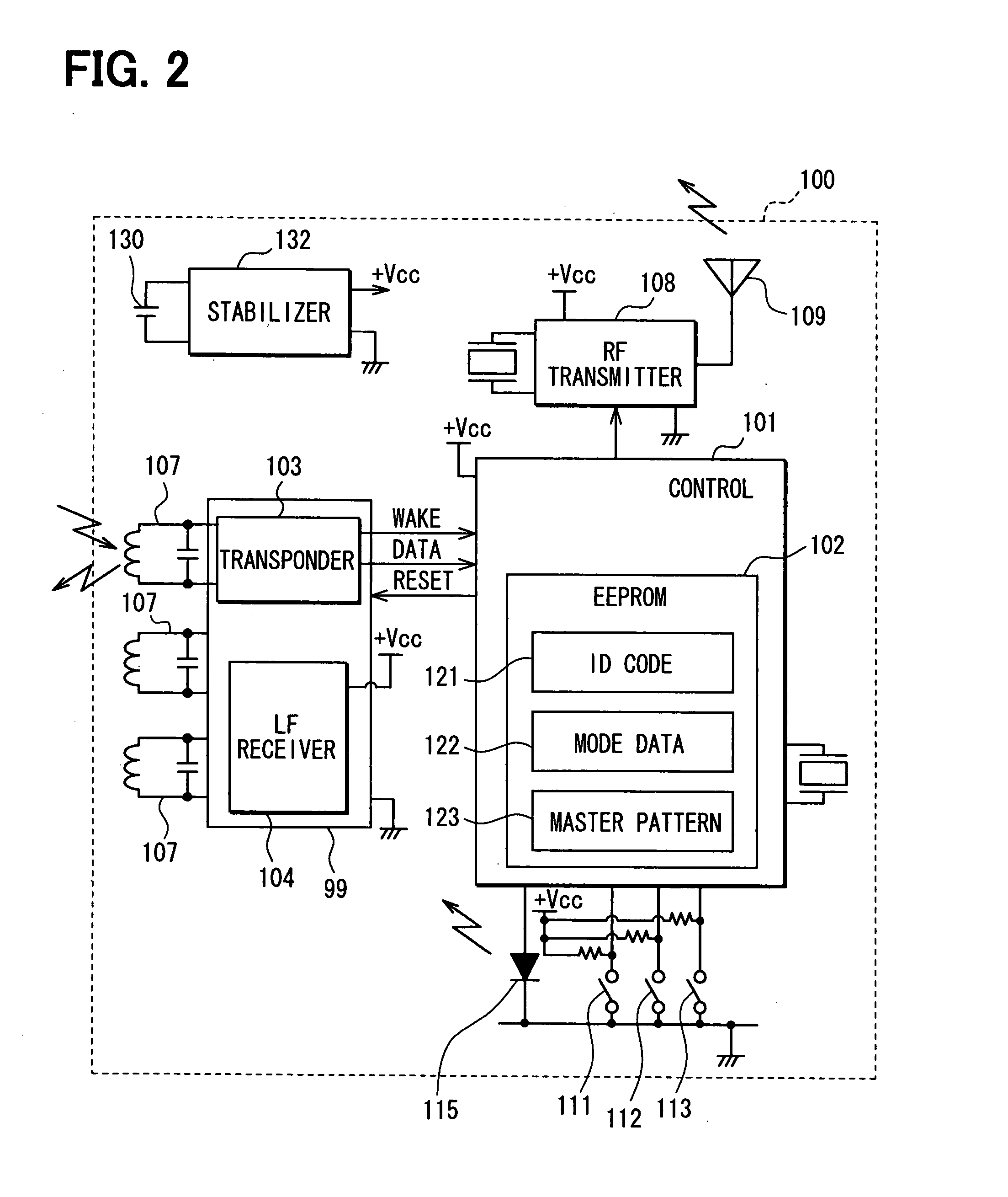
[0023] Referring first to FIG. 1, a vehicle door remote locking and unlocking control system 1 includes a vehicle wireless key (mobile device) 100 that is carried by a user of a vehicle, and an electronic control unit (ECU) 10 that is mounted in the vehicle. The control unit 10 refers to ID information through a wireless communication with the mobile device 100, and locks or unlocks doors of the vehicle and conducts the start control of an engine based on the reference results. Also, it is possible to lock or unlock the doors of the vehicle due to manipulation of manipulation units 111, 112 and 113 that are disposed in the mobile device 100 as a manipulation device.

[0024] The control unit 10 has a microcomputer 11 that mainly conducts hardware control....


PUM


Abstract

A wireless key includes a receiver circuit that operates with a built-in battery, and receives a polling radio wave for wireless key search and authentication from a vehicle, and a transmitter circuit that transmits a lock operation radio wave to a door based on the manipulation on a manipulation device. The wireless key is capable of changing over operation mode between a power saving mode that permits the operation of transmitting the lock operation radio wave by the transmitter circuit and stops the operation of receiving the polling radio wave by the receiving circuit, and a full power mode that permits the operation of transmitting the lock operation radio wave by the transmitter circuit and continues the reception by the receiver circuit.

Description

CROSS REFERENCE TO RELATED APPLICATION [0001] This application is based on and incorporates herein by reference Japanese Patent Application No. 2006-224231 filed on Aug. 21, 2006. FIELD OF THE INVENTION [0002] The present invention relates to a wireless key and a door remote control system having the wireless key for remote-controlling locking and unlocking of a door. BACKGROUND OF THE INVENTION [0003] In recent years, a large number of vehicles are equipped with a vehicle door remote locking and unlocking control system. The vehicle door remote locking and unlocking control system conducts wireless communication between a vehicle wireless key (electronic wireless key: mobile device) which is carried by a user (driver) and a vehicle electronic control unit (ECU) to lock or unlock a door. This system is known as a smart key system (e.g., JP 2005-264660A). [0004] The smart key system periodically polls the wireless key through the wireless communication from an in-vehicle device, so t...

Claims


Application Information

Patent Timeline
IPC IPC(8): B60R25/10B60R25/01B60R25/04B60R25/24B60R25/40E05B49/00
CPCB60R25/24B60R25/406G07C2009/00587G07C9/00309G07C9/00182B60R25/10E05B49/00
Inventor NAGAI, NOBUYOSHIOOTSUKA, MITSUGI
Owner DENSO CORP
Learn More