
Construction Configurations and Construction Methods of Steel Houses

a construction configuration and construction method technology, applied in the direction of girders, walls, joists, etc., can solve the problems of increasing the number of construction workers, the difficulty of field work, and the need to provide hold-down hardware and metal reinforcements, so as to improve the efficiency of field work and facilitate construction. , the effect of increasing the time and trouble in field work

Inactive Publication Date: 2008-02-28
NIPPON STEEL CORP
View PDF27 Cites 17 Cited by
  • Summary
  • Abstract
  • Description
  • Claims
  • Application Information

AI Technical Summary

Benefits of technology

The present invention provides a steel house construction that eliminates the need for heavy machines and scaffolds by completing walls one story after another. It also eliminates the shortcomings of the conventional platform construction method that requires hold-down and other reinforcing hardware. The invention reduces the need for field work and the time and trouble in field work increases. It includes a steel house construction configuration made by constructing a structural framework by assembling vertical frame studs and wall panels erected on a foundation and a floor panel, in which the vertical frame studs provided at intersections of the wall panels and corners are through studs continuing to upper stories, the walls of an upper story are constructed by connecting the wall panels for the upper story after the walls of a lower story have been constructed by connecting the wall panels for the lower story to said through vertical frame studs. The invention also includes the use of fasteners such as drill screws, bolts and one-side bolts to join the vertical frame studs and wall panels. The construction of the steel house according to the invention involves erecting through vertical studs continuing to an upper story on the ground, placing wall panels four sides of a rectangle constituting a room on a lower story and connected to the through vertical frame studs, mounting two opposite sides of a floor panel for an upper story on the upper ends of the wall panels on the two opposite sides of a lower story, connecting the other two opposite sides of the floor panel to through vertical frame studs, and constructing the walls and floors of upper stories by repeating the procedure.

Problems solved by technology

The need to provide such hold-down hardware and metal reinforcements complicates the structure of buildings.
The platform construction method just described requires intricate design that, in turn, makes field work difficult because connection of the wall panel 1 to the floor panel 3 and that of the wall panels 1 of the upper and lower stories require hold-down hardware 5, connection hardware 8 and other metal reinforcements.
If such metal reinforcements are eliminated or reduced in order to avoid an increase in the number of structural members and complicated design, construction becomes hazardous.
Furthermore, the conventional platform construction method tends to require intricate design because load transfer paths are complicated.
However, the technology disclosed in Japanese Unexamined Patent Publication No. 11-140975 defies a simple method practicable with the platform construction method in which unitized wall panels, which are prepared by fastening a structural surface member to a rectangular wall frame, are joined together, one story after another.
The technology disclosed in Japanese Unexamined Patent Publication No. 11-140975 involves a problem that the time and the trouble in field work increase because wall panel surface members must be attached at the construction site after all vertical frame studs extending to the uppermost story have been joined together.

Method used


Image

  • Construction Configurations and Construction Methods of Steel Houses
  • Construction Configurations and Construction Methods of Steel Houses
  • Construction Configurations and Construction Methods of Steel Houses

Examples


Embodiment Construction

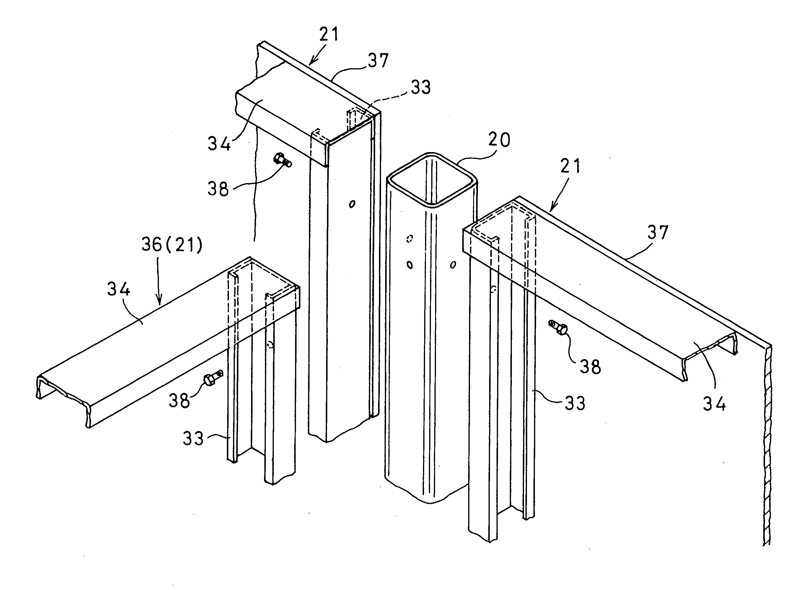
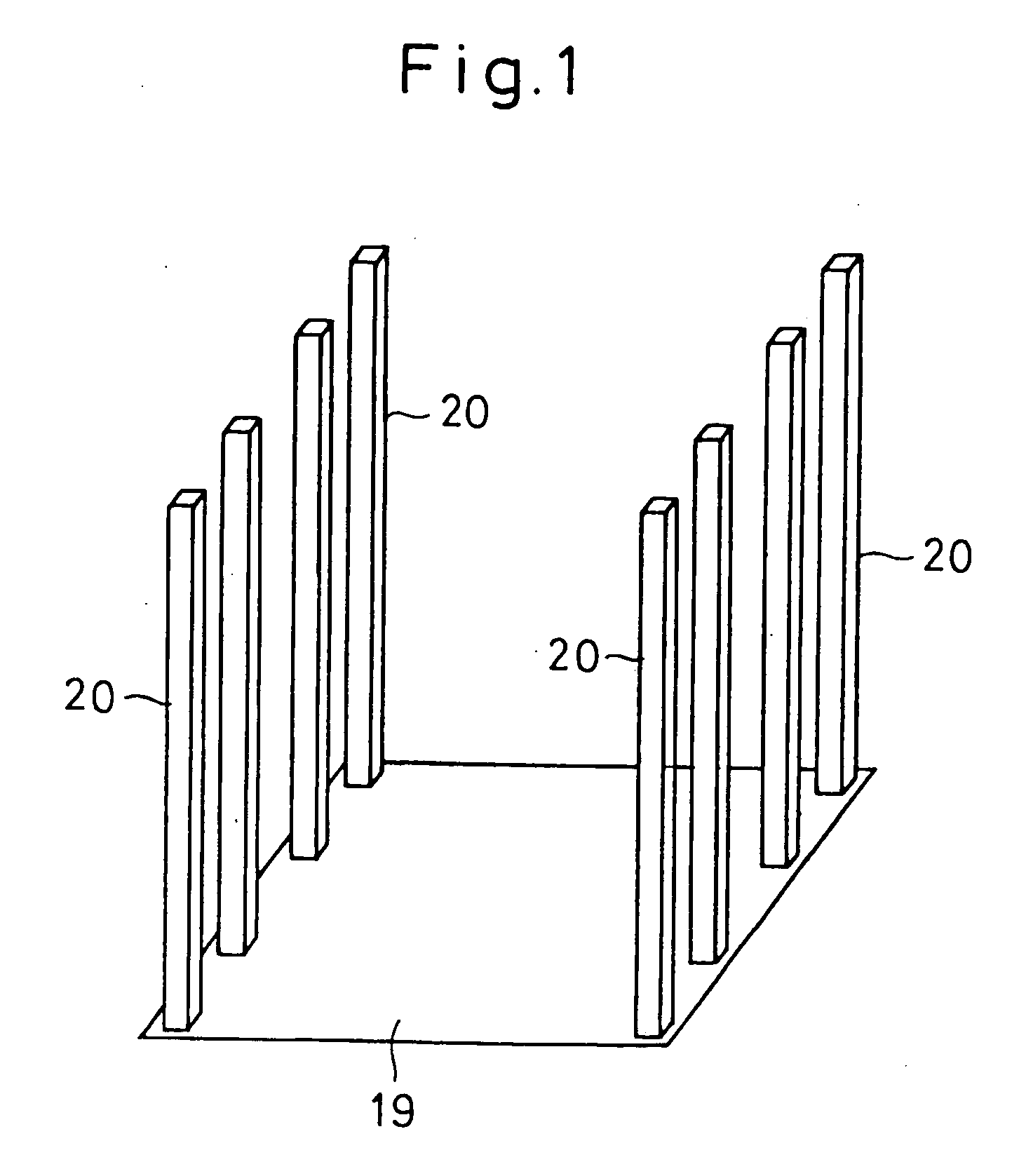
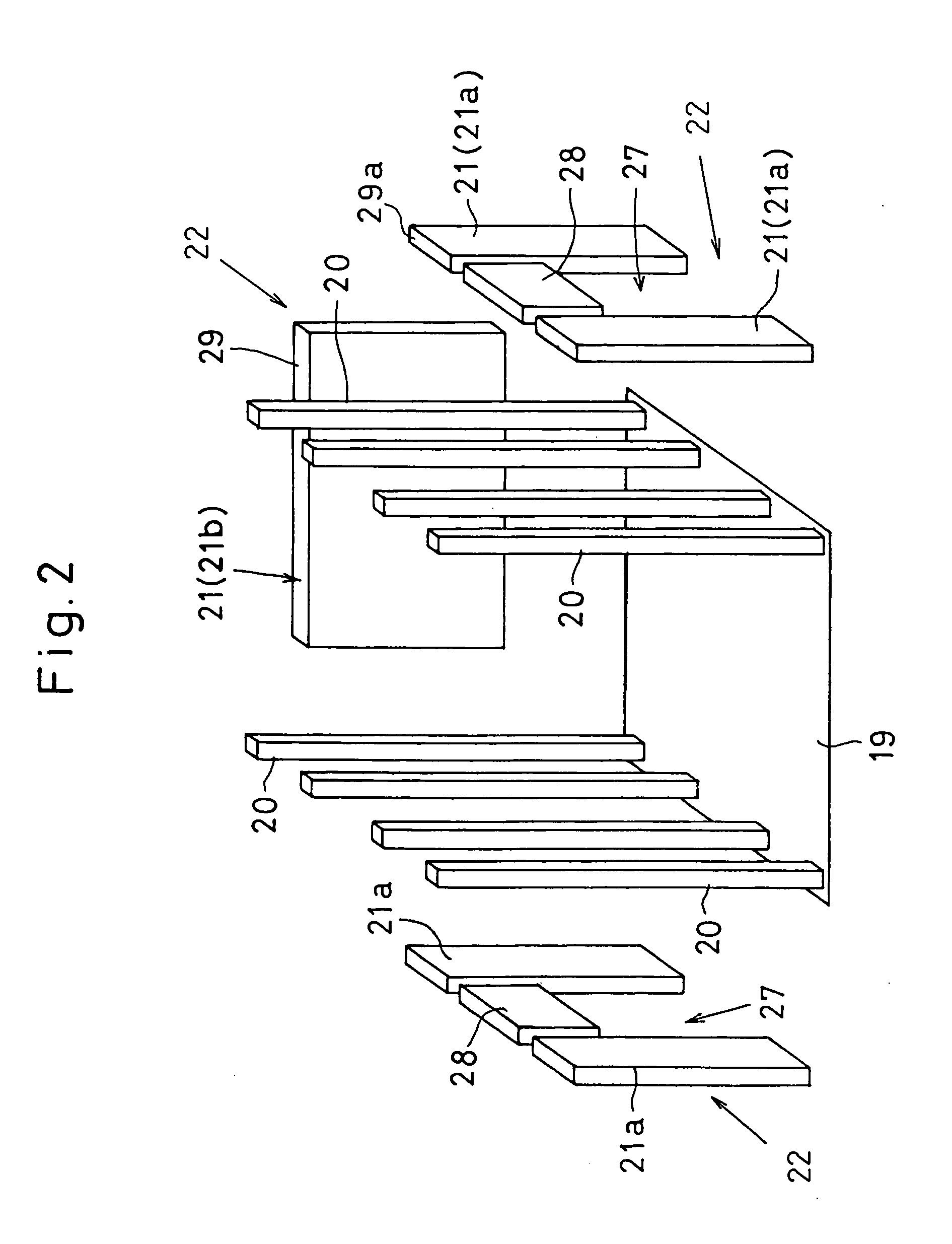
[0036]FIGS. 1 to 4 are schematic views illustrating steps for constructing a structural framework of a steel house in an embodiment according to the present invention. FIGS. 5(a) and 5(b) are detail views of a floor panel support structure. FIG. 6 is a perspective view showing wall panels being attached to a through vertical frame stud. FIG. 7(a) and 7(b) are perspective and vertical cross-sectional views of a wall panel. FIGS. 8(a), 8(b) and 9 are explanatory plan views illustrating steps to attach wall panels to through vertical frame studs.

[0037]A brief description of the present invention is given by reference to schematic views in FIGS. 1 to 4. According to the steel house panel construction according to the present invention, the floor 19 of the ground story is completed first and, then, multiple through vertical frame studs 20 are erected thereon along and, at given intervals, the four sides of a rectangle (FIG. 1). Next, the ground story wall 22 is completed by attaching wal...


PUM


Abstract

The present invention provides construction configurations and a construction method for steel houses that eliminate the shortcoming of the conventional platform construction method for steel houses that complicates the structure because of the need to use metal reinforcements without losing the advantage of the conventional method that facilitates the construction work by using wall panels.After constructing the ground story wall (lower story wall) 22 by attaching wall panels 21 for the ground story to through vertical frame studs 20 extending to upper floors, the second story wall (upper story wall) 23 is constructed by attaching wall panels 21 for the upper story to the through vertical frame studs 20. Of the wall panels 21 disposed along the four sides of the lower story, the top ends 29 of the two opposite wall panels 21b are positioned lower than the top ends 29a of the lower story wall panels 21a on the other two opposite sides. Both ends of the floor panel 24 are mounted on the lower top ends 29 of the wall panels 21b.

Description

TECHNICAL FILED[0001]The present invention relates to construction configurations and construction methods of steel houses.BACKGROUND ART[0002]Steel houses are generally defined as steel panel construction buildings comprising light gage frame members made from sheet steels not less than 0.4 mm and less than 2.3 mm in thickness and structural face members combined with said frame members. When building relatively low buildings, such as of two or three stories, with such steel members, building has conventionally been carried out by the platform construction method (the so-called frame-wall construction method) that completes one story after another by first completing the ground story by laying the floor thereof and placing the wall panels for one story and then mounting the floor panel of the upper story on the wall panels of the ground story, thus completing one story after another. This platform construction method has an advantage of eliminating the need for heavy machines and s...

Claims


Application Information

Patent Timeline
Patent Type & Authority Applications(United States)
IPC IPC(8): E04C3/32E04C2/00
CPCE04B1/08E04B1/24E04B2001/2484E04B2001/2481E04B1/2403E04H1/02E04H1/04E04B1/16E04B2/56E04B5/02E04B1/34315E04B1/34384E04B1/348E04B1/35E04B1/388
Inventor KAWAI, YOSHIMICHIFUJIHASHI, KAZUNORITOHNAI, SHIGEAKI
Owner NIPPON STEEL CORP
Learn More