
Deblocking filter, image encoder, and image decoder

a filter and image technology, applied in the field of deblocking filters, image encoders, image decoders, can solve the problems of inefficiency of operation, increase in processing time, and shortage of processing time, and achieve the effect of reducing processing tim

Inactive Publication Date: 2008-02-21
SOCIONEXT INC
View PDF26 Cites 76 Cited by
  • Summary
  • Abstract
  • Description
  • Claims
  • Application Information

AI Technical Summary

Benefits of technology

[0012]The present invention is made in view of the above problems, and the first object of the present invention is to provide a deblocking filter in which the processing time is reduced, and the second object of the present invention is to provide an image encoder and an image decoder which use such a deblocking filter.

Problems solved by technology

Therefore, if a group of four filtered pixels are stored as they are in the memory, the stored pixels are required to be read out from the memory for the next edge-filtering operation, so that the operation is not efficient.
However, since the vertically-filtered data are stored in the memory circuit in the horizontal (row) direction in the conventional horizontal-edge filtering, it is impossible to perform the horizontal-edge filtering until the operation of reading out the data of necessary pixels (the current-side pixels) are completed, so that the necessary processing time increases.
Therefore, shortage of the processing time occurs in particular in image processing for display in a large screen.

Method used


Image

  • Deblocking filter, image encoder, and image decoder
  • Deblocking filter, image encoder, and image decoder
  • Deblocking filter, image encoder, and image decoder

Examples


first embodiment

2.3.1 Construction of Deblocking Filter (First Embodiment)

[0058]FIG. 4 is a circuit block diagram indicating a deblocking filter according to the first embodiment of the present invention. The deblocking filter 113 of FIG. 4 comprises pixel selection circuits 113a and 113b, a timing controller 113c, a write-memory controller 113d, a read-memory controller 113e, a current-pixel-storing memory 113f, an upper-adjacent-pixel-storing memory 113g, a left-adjacent-pixel-storing memory 113h, a current-pixel selection circuit 113i, an adjacent-pixel selection circuit 113j, filter circuits 113k and 113m, a filtering-parameter holding circuit 113n, a delay circuit 113o, external-memory interfaces 113p and 113q, and an external memory 113r. Hereinafter, the current-pixel-storing memory may be referred to as the current memory, the upper-adjacent-pixel-storing memory may be referred to as the upper-adjacent memory, and the left-adjacent-pixel-storing memory may be referred to as the left-adjacen...

second embodiment

2.3.4 Construction of Deblocking Filter (Second Embodiment)

[0127]Hereinbelow, a deblocking filter according to the second embodiment of the present invention is explained below. In the following explanations of the second embodiment, basically only the differences from the first embodiment are described, and similar features and operations to the first embodiment are not explained below. FIG. 20 is a circuit block diagram indicating a deblocking filter according to the second embodiment of the present invention.

[0128]The deblocking filter 113-1 of FIG. 20 according to the second embodiment is different from the first embodiment only in that the arrangement and the functions of the current-pixel selection circuit 113s in the deblocking filter 113-1 of FIG. 20 are different from the arrangement and the functions of the current-pixel selection circuit 113i in the deblocking filter 113 of FIG. 4.

[0129]The output terminals of the delay circuit 113o and the current memory 113f are connect...


PUM


Abstract

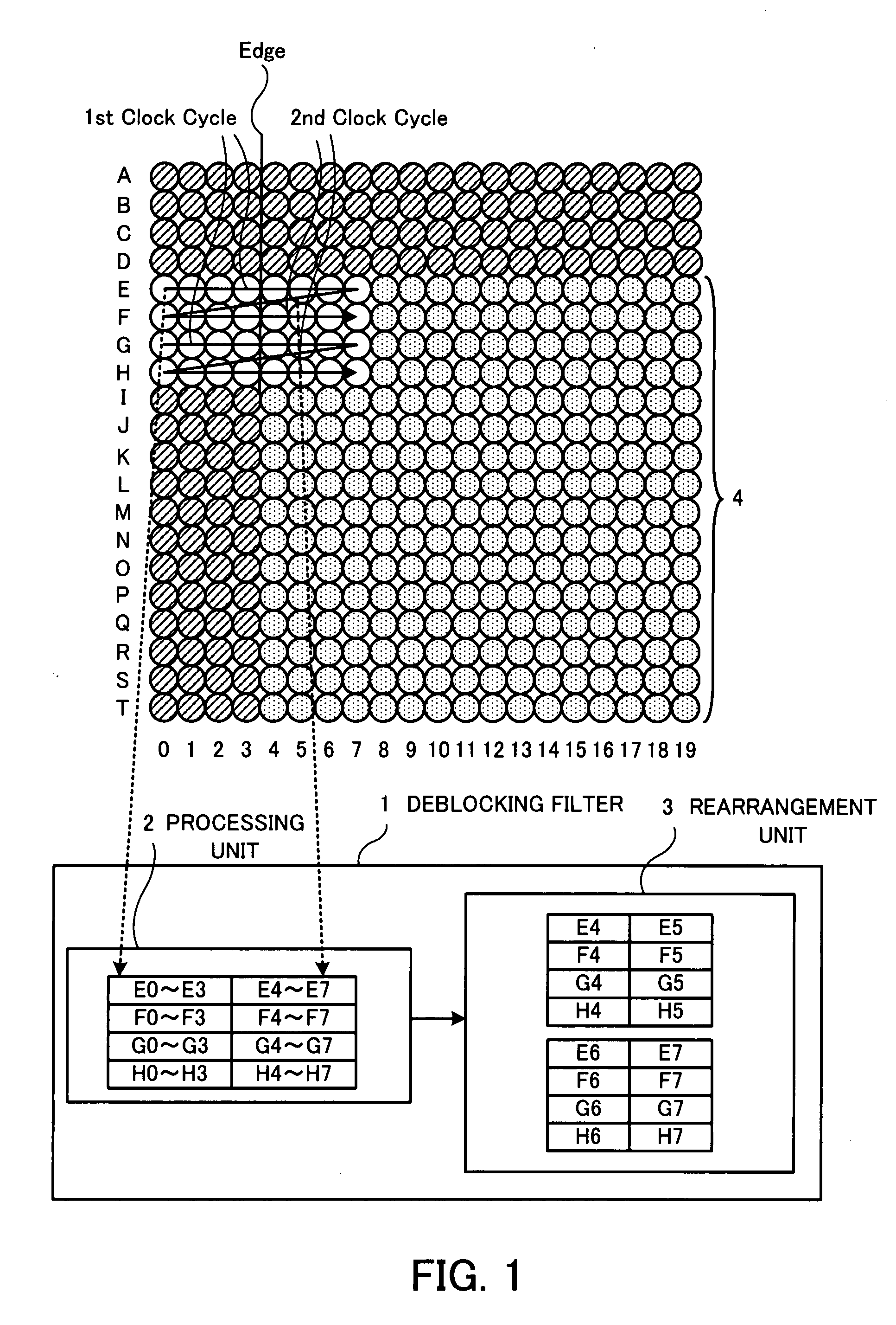
A deblocking filter, an image encoder, and an image decoder perform edge-filtering of moving-image data which can be divided into blocks, on groups of a predetermined number of pixels arrayed across edges between the blocks, and include: a processing unit concurrently performing column-direction-edge filtering on more than one first group of pixels which are arrayed in rows across ones of the edges oriented in a column direction, the ones of the edges belonging to a macroblock to be currently processed; and an rearrangement unit rearranging pixels being included in the more than one first group of pixels and the macroblock and having been processed by the processing unit, into more than one second group of pixels in respective columns.

Description

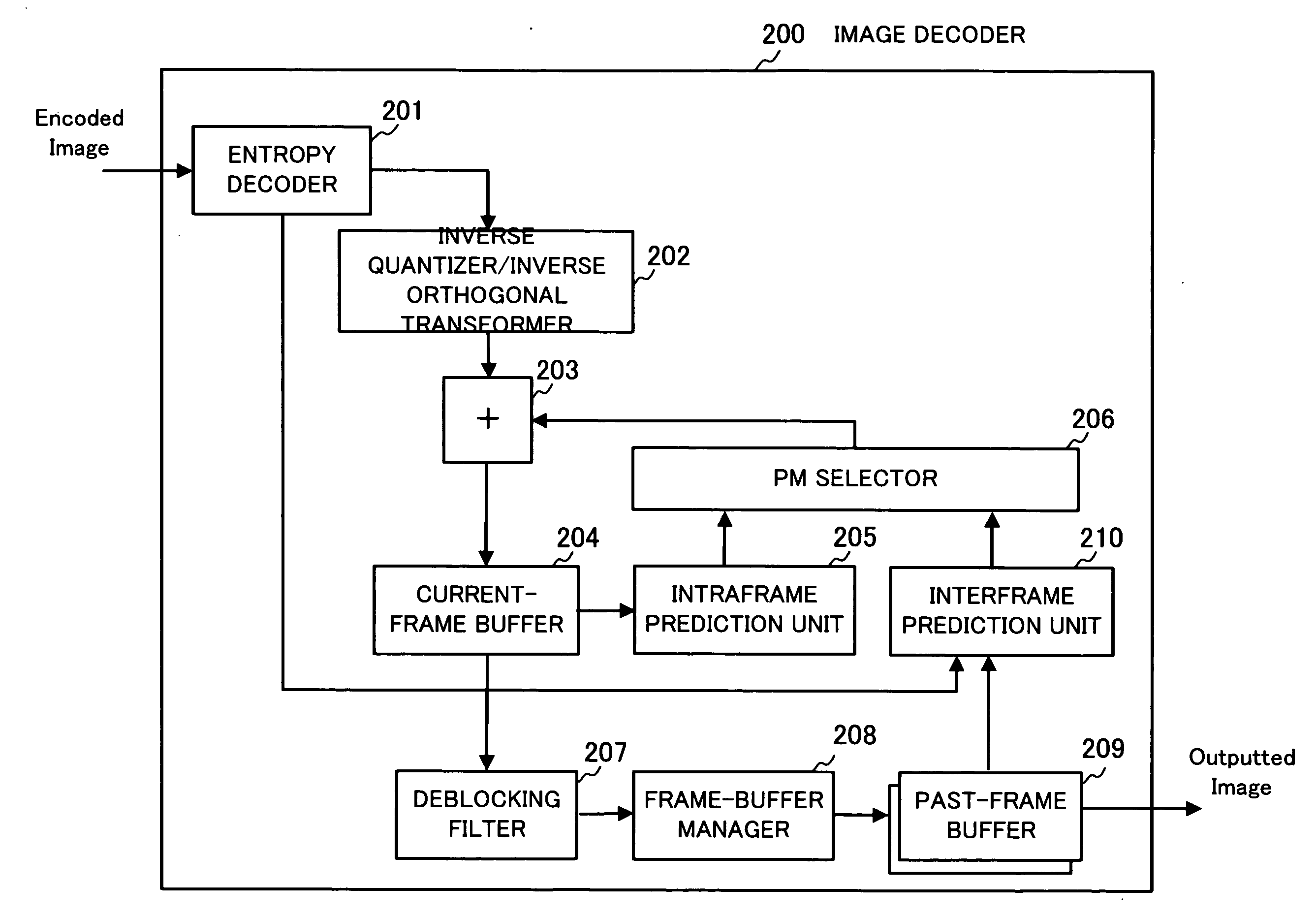
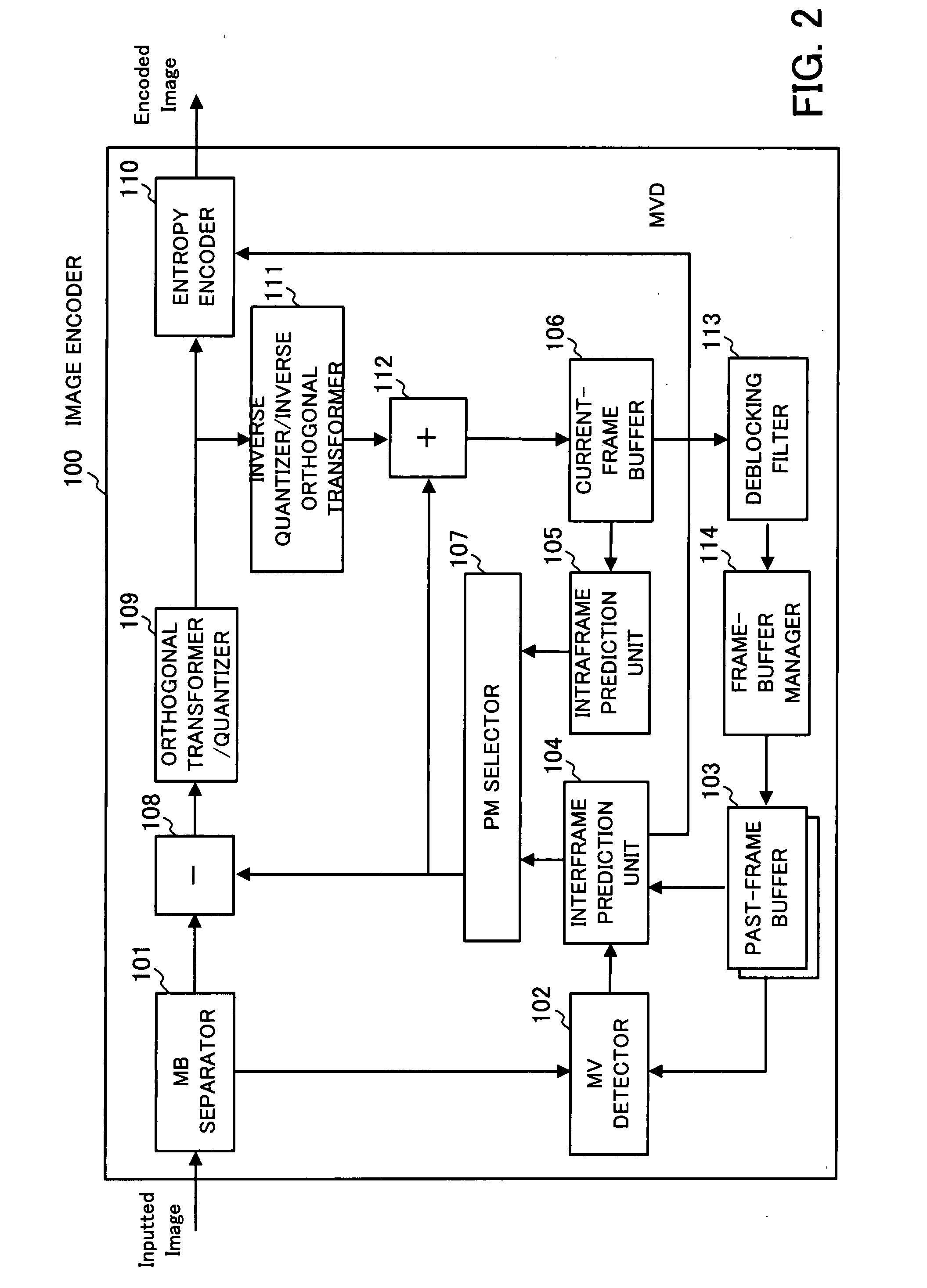
CROSS-REFERENCE TO RELATED APPLICATIONS[0001]This application is based upon and claims the benefits of priority from the prior Japanese Patent Application No. 2006-222173, filed on Aug. 17, 2006, the entire contents of which are incorporated herein by reference.BACKGROUND OF THE INVENTION[0002]1) Field of the Invention[0003]The present invention relates to a deblocking filter which reduces block distortion, and also relates to an image encoder and an image decoder which use such a deblocking filter.[0004]2) Description of the Related Art[0005]Currently, the MPEG (Moving Picture Expert Group) standards, the ITU-T H.264 standard, and the like are known as technical standards specifying techniques for compression encoding of a video signal. According to the MPEG or H.264 standards, the size of the basic macroblock is 16×16 pixels. In addition, according to the H.264 standard, the blocks with the size of 4×4 pixels can also be used when necessary. In particular, according to the H.264 s...

Claims


Application Information

Patent Timeline
IPC IPC(8): H04B1/66G06K9/40H04N19/117H04N19/00H04N19/134H04N19/16H04N19/176H04N19/182H04N19/189H04N19/423H04N19/436H04N19/51H04N19/60H04N19/85H04N19/86H04N19/91
CPCH04N19/176H04N19/46H04N19/61H04N19/117H04N19/527H04N19/186H04N19/82H04N19/423H04N19/436H04N19/14
Inventor KAWA, TAKEYOSHI
Owner SOCIONEXT INC
Learn More