Temperature sensor, temperature control device, temperature controller and temperature-control method

Active Publication Date: 2008-02-21
KOMATSU LTD
View PDF10 Cites 302 Cited by
  • Summary
  • Abstract
  • Description
  • Claims
  • Application Information

AI Technical Summary

Benefits of technology

[0019] An object of the present invention is to provide a temperature sensor that can secure a sufficient measurement accuracy without influencing a temperature distribution of an object to be measured and to provide a temperature control device that includes the temperature sensor.
[0020] In addition, another object of the present invention is to provide a temperature controller and a temperature controlling method with which an influence of a natural convection is avoided and a temperature of an object to be temperature-controlled can be controlled with a stable control command fluctuation and settling time.

Problems solved by technology

Particularly in photolithography, a chemically-amplified resist agent used for forming a linewidth of 150 nm or below is vulnerable to an influence of temperature changes.
In this case, since an actual temperature of the wafer 50 to be controlled is unknown, there is a difficulty in accurately performing a temperature control of the wafer 50.
Thus, the temperature sensor is influenced by the heat of the heating plate in measuring the temperature, whereby a measurement accuracy of the wafer temperature is not sufficiently secured.
Accordingly, the measurement accuracy of the wafer temperature is not sufficiently secured.
In this case, the temperature of the hot place is also largely fluctuated in accordance with the control command, whereby a subsequent temperature control may not be smoothly performed.

Method used


Image

  • Temperature sensor, temperature control device, temperature controller and temperature-control method
  • Temperature sensor, temperature control device, temperature controller and temperature-control method
  • Temperature sensor, temperature control device, temperature controller and temperature-control method

Examples


first embodiment

[1-1] Overall Arrangement

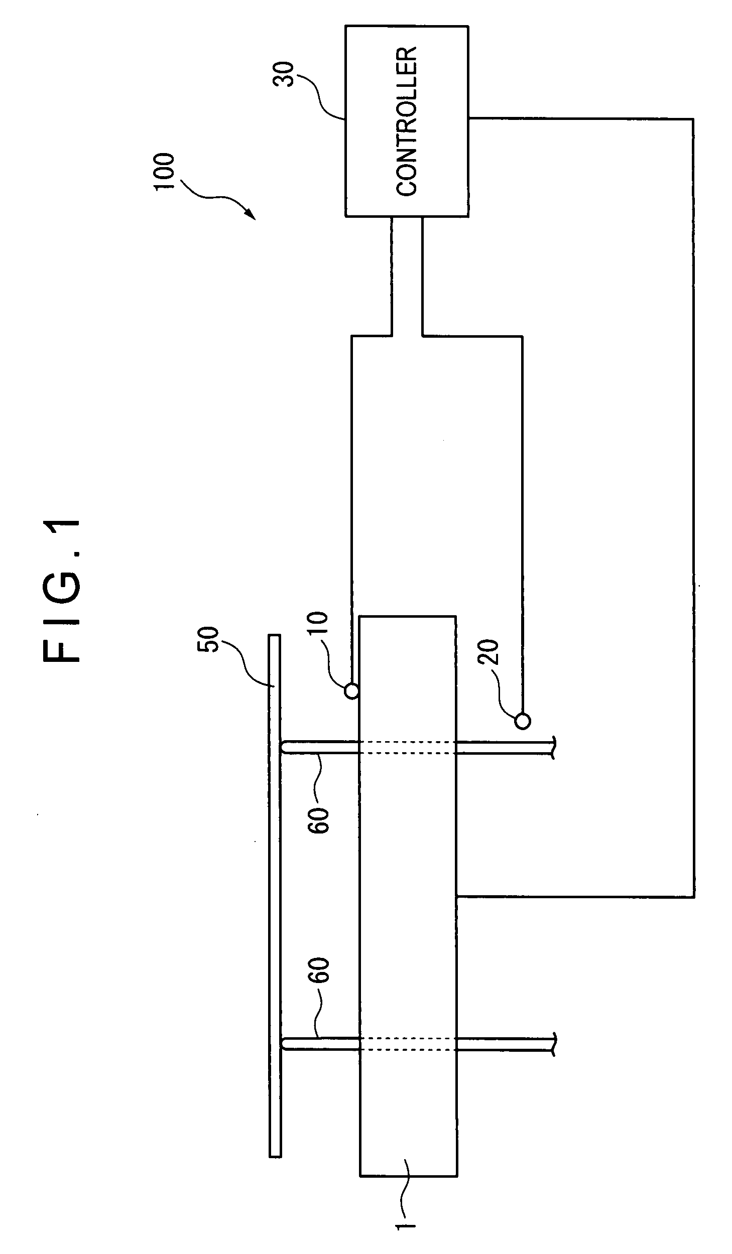
[0064] In FIG. 1 showing an overall arrangement of a temperature controller 100 according to a first embodiment of the present invention, the temperature controller 100 includes a hot plate 1 (temperature control device), a temperature sensor 10, a position sensor 20 and a controller 30.

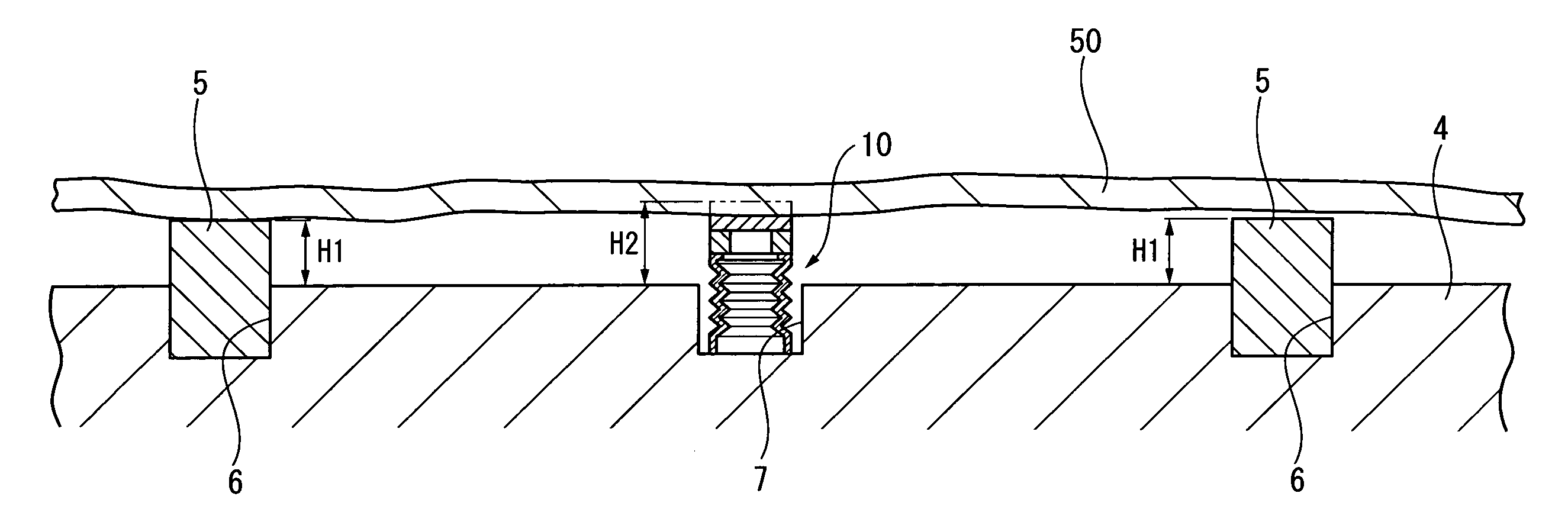
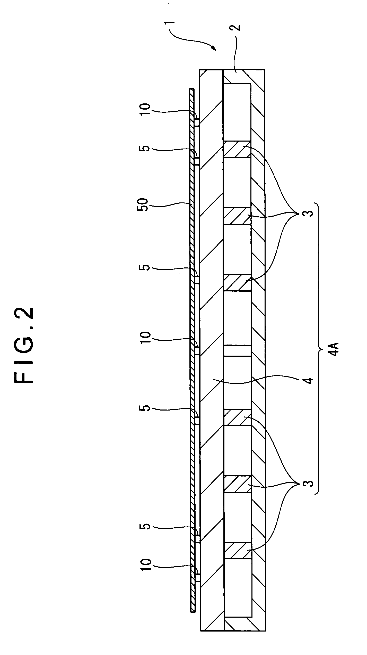
[0065] The hot plate 1 is a device for adjusting a temperature of a wafer 50 (measured object, to-be-temperature-controlled object) by heating, and is adapted to control an amount of the applying heat. The wafer 50 having been transferred by a transfer robot (not shown) is once placed on a lift pin 60 that is adapted to be lifted up and down while penetrating the hot plate 1. Subsequently, by lifting down the lift pin 60, the wafer 50 is mounted on the hot plate 1.

[0066] A temperature sensor 10 is attached to a surface of the hot plate 1 to contact a back surface of the wafer 50 that has been lowered in accordance with the lifting down of the lift pin 60. The temperature ...

second embodiment

[0112] Next, a second embodiment according to the present invention will be described referring to FIG. 10.

[0113] In the above-described first embodiment, the supporting portion 12 of the temperature sensor 10 is directly attached to the upper portion 131 of the bellows 13.

[0114] In contrast, the second embodiment is different in that the supporting portion 12 is attached to the upper portion 131 of the bellows 13 via an adapter 16.

[0115] Specifically, as shown in FIG. 10, the temperature sensor 10 according to the present embodiment includes the temperature-sensing portion 11, the supporting portion 12, bellows 13 and the adapter 16. A biasing member according to the present embodiment includes the bellows 13 and the adapter 16, and an end portion of the biasing member includes the upper portion 131 of the bellows 13 and the adapter 16.

[0116] The adapter 16, which is made of ceramics, is attached to the upper portion 131 of the bellows 13. In the vicinity of the center of the a...

third embodiment

[0119] Next, a third embodiment according to the present invention will be described referring to FIG. 11.

[0120] In the above-described first and second embodiments, the holes 112C of the temperature-sensing portion 11, the through holes 121A, 122B of the supporting portion 12 and the hole 161 of the adapter 16 are linearly aligned in the temperature sensor 10. On the other hand, the wire 14 bonded to the platinum pattern 112B of the temperature-sensing portion 11 is drawn to the bellows 13 side through the though holes 121A, 122B and the hole 161.

[0121] In contrast, the third embodiment is different in that a through-via 17 is provided from the platinum pattern 112B of the temperature-sensing portion 11 to the bellows 13, and that the through-via 17 is extended toward the center of the bellows 13 by an adapter electrode 162.

[0122] Specifically, in the temperature sensor 10 according to the present embodiment, as shown in FIG. 11, the through-via 17 extends from the platinum patt...


PUM


Abstract

A temperature sensor (10) includes: a temperature-sensing portion for measuring a temperature of an object (50) by contacting the object; and a supporting portion for supporting the temperature-sensing portion from a side opposite to a contact surface, the supporting portion having a space at a portion partially corresponding to the temperature-sensing portion. A temperature controller includes: a temperature control device; the temperature sensor (10) for measuring the temperature by contacting the object (50); and a controller for controlling the temperature control device. The controller includes: a mounting-state judging means for judging a mounting-state of the object (50); a switching means for switching a control gain and a target temperature of the temperature control device based on the judging result; and a control-command generating means for generating a control command based on the control gain, the target temperature and a measurement value of the temperature sensor (10).

Description

BACKGROUND OF THE INVENTION [0001] 1. Field of the Invention [0002] The present invention relates to a temperature sensor, a temperature control device and a temperature controller that include the temperature sensor, and a method of temperature control, particularly to a temperature sensor, a temperature control device, a temperature controller and a method of temperature control for a semiconductor wafer. [0003] 2. Description of Related Art [0004] In recent years, along with demands for a performance enhancement and a cost reduction of semiconductor devices, there have been demands for a miniaturization, an improvement of yield, an improvement of throughput and a high-mix low-volume manufacturing in manufacturing processes of semiconductor devices. In order to meat these demands, a high accuracy is required in a circuit linewidth. The accuracy of the circuit linewidth depends on a wafer temperature inside a chamber in a heat treatment process. Accordingly, in the manufacturing pr...

Claims


Application Information

Patent Timeline
IPC IPC(8): H01L21/66G01K1/00F24F11/76
CPCG01K1/143G05D23/2217G01K7/186G05D23/1919G05D23/22
Inventor BANDOH, KENICHI
Owner KOMATSU LTD
Why Eureka
Try Eureka