
System and Method for Assigning Channels in a Wireless Network

a wireless network and wireless network technology, applied in the field of communication systems, can solve the problems of increased operating costs, unsatisfactory signal encounter, and inability to meet the signal from the base station, and achieve the effect of reducing or eliminating at least some of the disadvantages and problems

Inactive Publication Date: 2008-02-21
FUJITSU LTD
View PDF26 Cites 54 Cited by
  • Summary
  • Abstract
  • Description
  • Claims
  • Application Information

AI Technical Summary

Benefits of technology

[0006]Particular embodiments provide a system and method for assigning channels in a wireless network that substantially eliminates or reduces at least some of the disadvantages and problems associated with previous methods and systems.
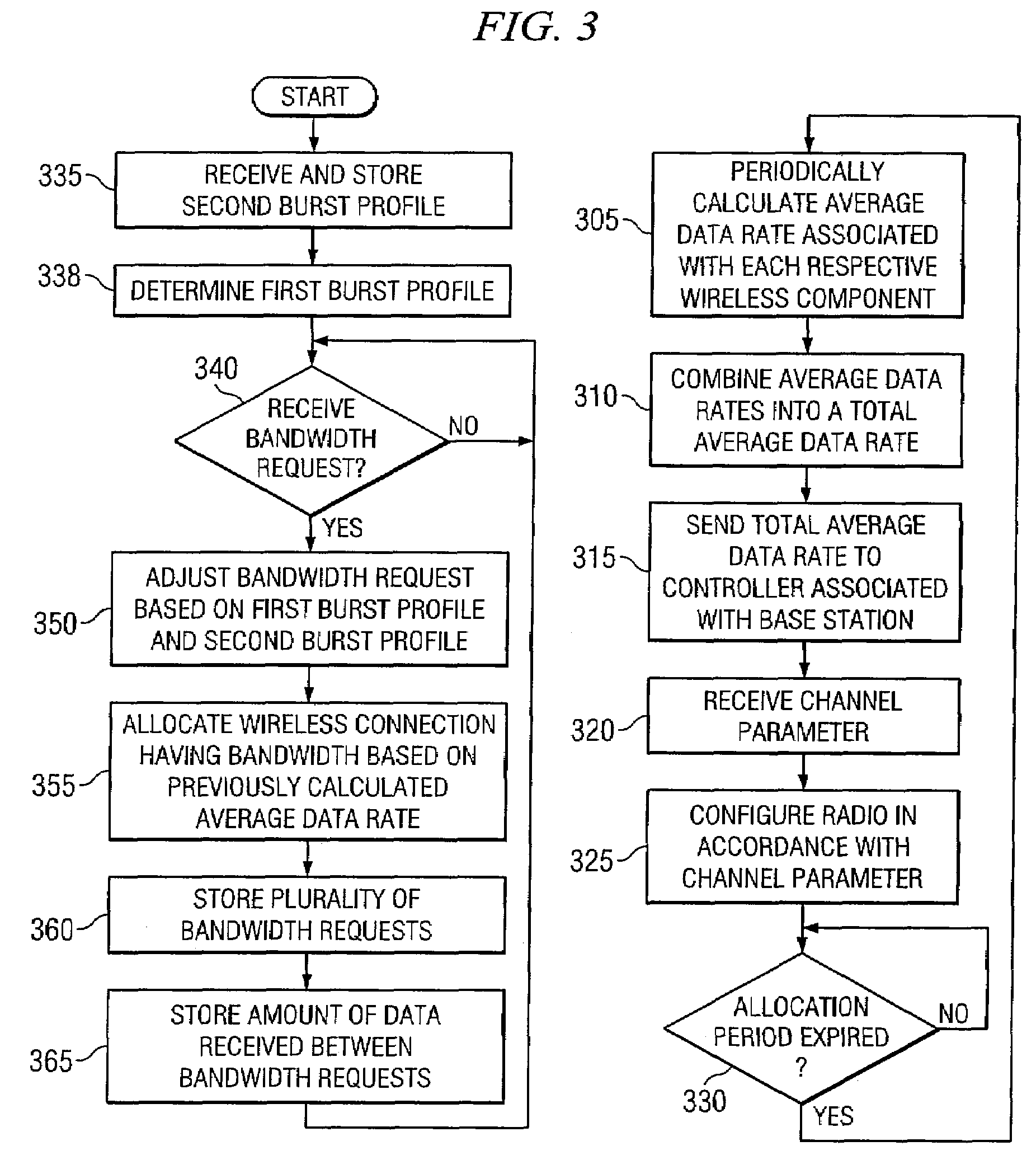
[0017]Technical advantages of particular embodiments include allocating endpoints with bandwidth based on an average data rate. Accordingly, bandwidth is allocated based on information representing a statistically longer period of time as opposed to wireless networks that grant bandwidth based solely on the most recent bandwidth request. Another advantage of particular embodiments includes periodically sending the average data rate to a controller for channel allocation. Accordingly, the amount of traffic sent between base stations and relay stations is reduced compared to wireless networks in which relay stations or base stations simply forward each bandwidth request they receive.

Problems solved by technology

This can often be difficult in areas where the signal from the base station encounters interference (e.g., at the edge of its range, in areas where the coverage of two bases stations overlap, within a tunnel or building).
However, this may not be desirable because of the increased operating costs and the limited access to backhaul links.
The capacity of this channel is finite and in some situations may be insufficient to support the traffic demands within a particular relay station's cell.

Method used


Image

  • System and Method for Assigning Channels in a Wireless Network
  • System and Method for Assigning Channels in a Wireless Network
  • System and Method for Assigning Channels in a Wireless Network

Examples


Embodiment Construction

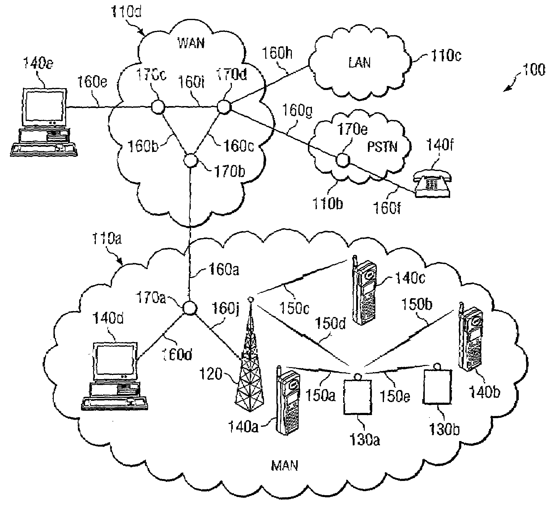
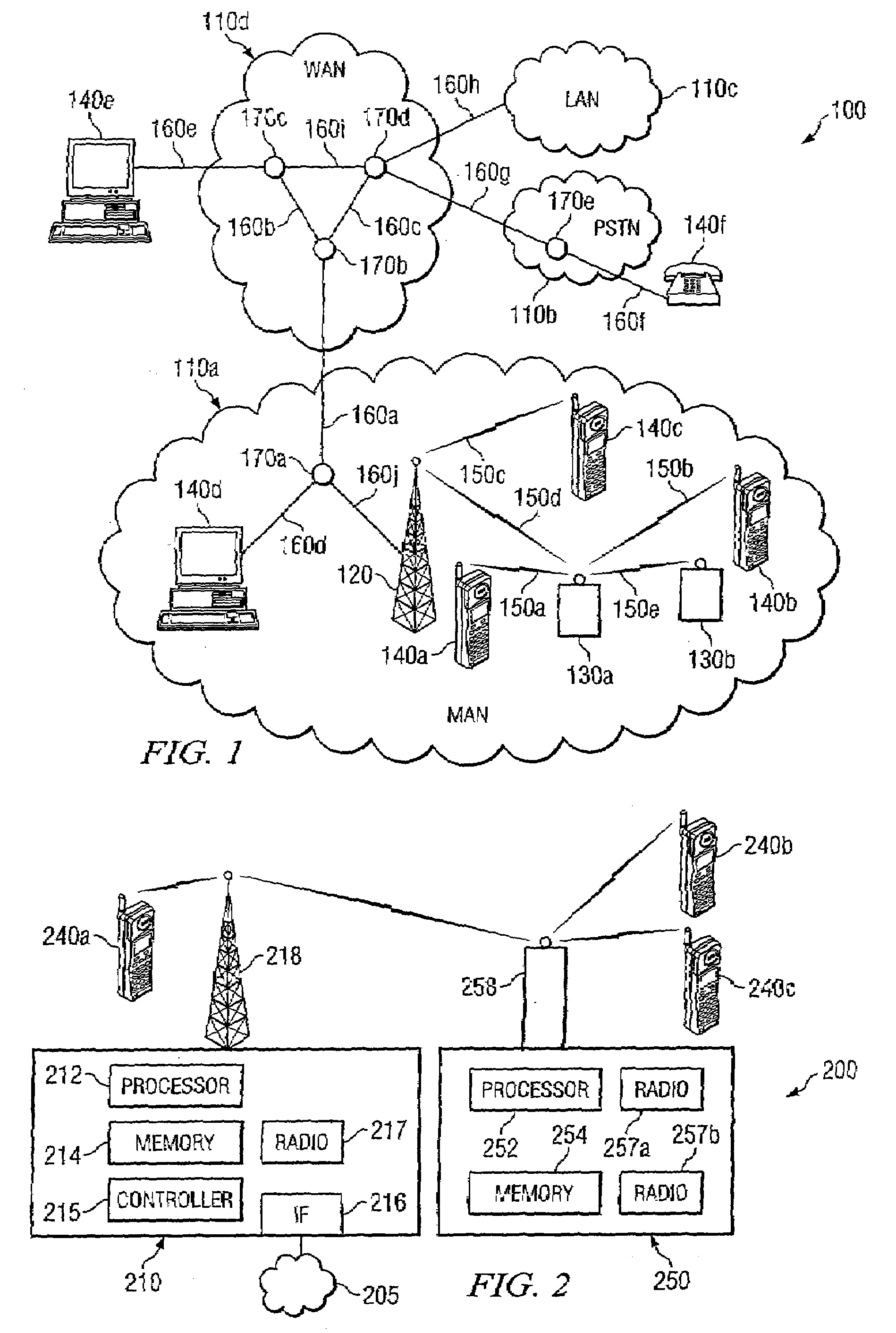
[0023]FIG. 1 illustrates a communication system comprising various communication networks, in accordance with a particular embodiment. Communication system 100 may be comprised of multiple networks 110. Each network 110 may be any of a variety of communication networks designed to facilitate one or more different services either independently or in conjunction with other networks. For example, networks 110 may facilitate internet access, online gaming, file sharing, peer-to-peer file sharing (P2P), voice over internet protocol (VoIP) calls, video over IP calls, or any other type of functionality typically provided by a network. Networks 110 may provide their respective services using any of a variety of protocols for either wired or wireless communication. For example, network 110a may comprise an 802.16 wireless network, popularly known as WiMAX, which may include base stations (e.g., base station 120) and relay stations (e.g., relay stations 130). Network 110a may provide for the ...


PUM


Abstract

A method for assigning channels in a wireless network includes receiving from each of a plurality of a first type of wireless components a total average data rate. Each total average data rate is based on an average data rate for each of a first plurality of a second type of wireless components coupled to the respective first type of wireless component. The method also includes determining at least one channel parameter for a first wireless component of the plurality of the first type of wireless components based on a ratio of the total average data rate associated with the respective first wireless component to the total average data rate associated with the plurality of the first type of wireless components. The method further includes allocating a channel to the first wireless component based on the determined at least one channel parameter.

Description

RELATED APPLICATIONS[0001]This application claims priority to U.S. patent application Ser. No. 60 / 822861, entitled “MANAGING A WIRELESS NETWORK,” which was filed on Aug. 18, 2006.TECHNICAL FIELD OF THE INVENTION[0002]This invention relates in general to communication systems and, more particularly, to a system and method for assigning channels in a wireless network.BACKGROUND OF THE INVENTION[0003]While broadband network services and Voice over IP (VoIP) products continue to grow and expand, so does the demand for wireless network functionality. To help meet this demand networks are being developed that use multiple base stations, relay stations, access points or points of contact. One emerging technology is 802.16, popularly known as WiMAX. WiMAX provides broadband wireless access, with a single base station providing coverage over a large area (theoretically up to 31 miles). Other wireless networking technologies include Third Generation (3G), Third Generation Partnership Project ...

Claims


Application Information

Patent Timeline
IPC IPC(8): H04J1/16H04Q7/00H04W74/08
CPCH04B7/2606H04W8/24H04W84/047H04W72/044H04W28/18H04W28/20
Inventor CHEN, WEI-PENGZHU, CHENXIHAMADA, TAKEOAGRE, JONATHAN R.
Owner FUJITSU LTD
Learn More