Direct user plane tunnel delivery of broadcast and multicast traffic

Active Publication Date: 2008-02-14
INTELLECTUAL VENTURES II
View PDF10 Cites 37 Cited by
  • Summary
  • Abstract
  • Description
  • Claims
  • Application Information

AI Technical Summary

Benefits of technology

[0006]Overload traffic conditions for multimedia services may be reduced by transmitting the traffic related to broadcasting multimedia over a first wireless network (defined by one RAT), and the associated control information over a second wireless network (defined by a substantially different RAT). The two networks may operate on substantially different frequency bands. Thus, the wireless terminal may receive a pIurality of signals originating from a pIurality networks.
[0007]A mobile operator may have both a paired and an unpaired spectrum. In the unpaired spectrum, the mobile radio technology may use Time Division Duplexing (TDD). In the paired spectrum, the mobile radio technology may use Frequency Division Duplexing (FDD). The multicast traffic is highly asymmetric. Thus, the multicast traffic is adequately matched to the unpaired spectrum, in which the ratio of downlink to uplink traffic may be adjusted to reflect the traffic demand. Moreover, the ratio may be adjusted such that the entire unpaired spectrum is dedicated to downlink. In this way, maximum utilization of the available spectrum is achieved. Under this scenario, the return channel is no longer present in the unpaired spectrum, and the user relies on the paired spectrum to provide the return channel.

Problems solved by technology

However, the existing UMTS air-interface and overall network architecture are not adequate to deliver high quality, bandwidth-demanding multimedia content, such as television for a large number of users.
Because MBMS is intended to serve a large user population, the high volume of broadcast / multicast traffic and the number of processing nodes along its path impose a significant performance strain on the existing core network and UTRA elements of the UMTS network.

Method used


Image

  • Direct user plane tunnel delivery of broadcast and multicast traffic
  • Direct user plane tunnel delivery of broadcast and multicast traffic
  • Direct user plane tunnel delivery of broadcast and multicast traffic

Examples


Embodiment Construction

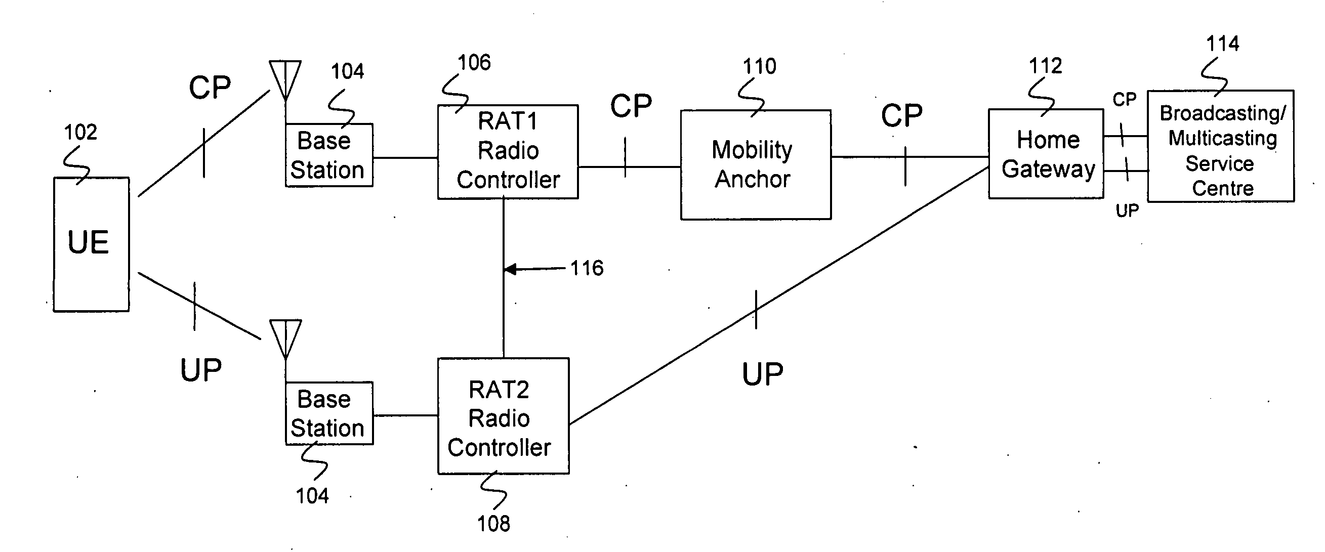
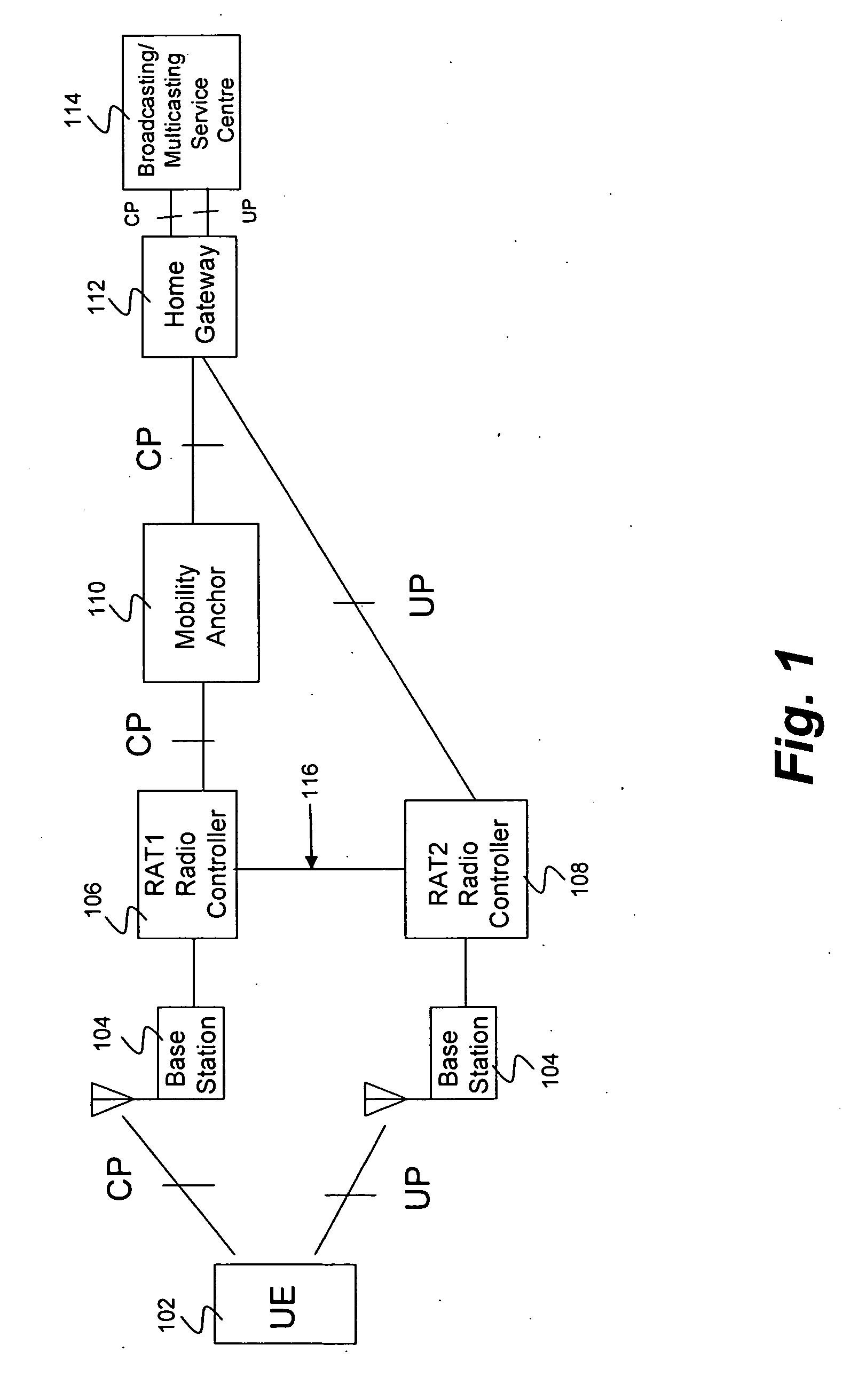
[0016]FIG. 1 illustrates an exemplary embodiment of the logical architecture of a network with a point-to-multipoint service center (e.g., an MBMS service center). A first network is defined by RAT1, and a second network is defined by RAT2. Each RAT is implemented by a radio controller (e.g., RAT1 radio controller 106 and RAT2 radio controller 108). The radio controller (RC) is the control element in the radio access network (RAN) responsible for controlling the base stations 104 of a specific RAT. The RC carries out radio resource and mobility management functions. This is the point in the network where encryption may be done before user data is sent to and from the mobile UE 102.

[0017]The UE 102 communicates with RAT1 and RAT2 via base stations 104 coupled to the RAT1 RC 106 and RAT2 RC 108. The UE wireless terminal 102 includes a first receiver, a second receiver, and a transmitter. The UE 102 may receive signals simultaneously from RAT1 and from RAT2. In other words, the first r...


PUM


Abstract

The establishment and reception of a service, such as a multimedia service, over different networks is described. A first and second network coupled by a home gateway may respectively employ first and second radio access technologies. An interface between the radio access technologies may communicate downlink channel setup requests. Uplink and downlink control signals are communicated via a first network. In response to the exchange of uplink and downlink control signals via a first network, multimedia data is received via the second network.

Description

BACKGROUND OF THE INVENTION[0001]Mobile operators worldwide have launched streaming real-time services (such as mobile TV and radio) over their existing 3G Universal Mobile Telecommunications System (UMTS) networks. However, the existing UMTS air-interface and overall network architecture are not adequate to deliver high quality, bandwidth-demanding multimedia content, such as television for a large number of users. Consequently, the 3GPP standards consortium identifies optimizations in the UTRAN and the core network system architecture that will allow the deployment of broadcasting-type applications over a UMTS air-interface and core network.[0002]The add-on framework to the UMTS system architecture in a family of 3GPP specifications is called Multimedia Multicasting / Broadcasting Service (MBMS). The MBMS framework identifies the modifications needed in the UMTS Radio Access Network (RAN) and describes service aspects, such as security and charging in a set of 3GPP specifications (s...

Claims


Application Information

Patent Timeline
IPC IPC(8): H04Q7/00H04W4/06H04W76/02H04W88/06H04W88/16
CPCH04W76/002H04W28/0289H04W88/16H04W88/06H04W76/40H04W36/0007H04W36/142H04W76/10H04W4/06H04W36/10H04L67/14
Inventor ZISIMOPOULOS, HARISWORRALL, CHANDRIKA K.JONES, ALAN EDWARD
Owner INTELLECTUAL VENTURES II
Why Eureka
Try Eureka