
Electrostatic chuck

Inactive Publication Date: 2008-02-14
SHINKO ELECTRIC IND CO LTD
View PDF4 Cites 32 Cited by
  • Summary
  • Abstract
  • Description
  • Claims
  • Application Information

AI Technical Summary

Benefits of technology

[0013] It has been known that a chucking operation resulting from a gradient force can be used to chuck a work made of an electrical insulating material such as a glass substrate by the use of an electrostatic chuck. However, a chucking force resulting from a Coulomb force also acts on the work made of an electrical insulating material such as a glass substrate. The inventor has found that the chucking operation resulting from the Coulomb force effectively serves to chuck a work made of an electrical insulating material, particularly a large-sized work, owing to a form of an electrode pattern. The invention is to provide an electrostatic chuck which can effectively chucks and supports a work made of an electrical insulating material by effectively generating the chucking operation resulting from the Coulomb force.
[0019] Further, when the area of the chucking surface is 0.6 m2 or more, the chuck body can be effectively used for an apparatus for chucking a large-sized work having an area of 0.6 m2 or more.
[0020] Further, when the chuck body is formed of a dielectric material having a volume resistivity of 1013 Ω·cm or more, it is possible to effectively chuck and support the work made of an electrical insulating material such as a glass substrate.
[0022] Further, when the positive and negative electrodes are provided in layers separated from each other in a thickness direction of the chuck body, the area ratio of the electrodes to the chucking surface of the chuck body can be easily set to be increased while problems, such as electrical discharge between the electrodes, are avoided.
[0023] In an electrostatic chuck according to the invention, the area ratio of positive and negative electrodes to the chucking surface of the chuck body is in the range of 60% to 90% so that a Coulomb force can be effectively generated for a work made of an electrical insulating material such as a glass substrate. Accordingly, it is possible to reliably chuck and support even a large-sized work.

Problems solved by technology

However, the chucking operation resulting from the gradient force is not relatively large.
However, a sufficient chucking force may not be obtained when a large-sized, heavy glass substrate having a side of 1 m such as a LCD panel is delivered.
However, when a work in which a circuit is formed on the surface of a substrate such as a LCD panel is handled and when a high voltage is applied to the electrodes, insulation breakdown may take place in the circuit or the work may be damaged by arc discharge.
Accordingly, a delivery error may occur, or a high voltage may be generated in the circuit formed on the surface of the glass substrate and the circuit may be damaged.
Since there are many cases where the charging of the glass substrate which is an insulating material is generated from the inside thereof, it is not effective to use discharging means, such as an ionizer, which radiates ions from outside for neutralization.
The work may move out of the original position thereof and therefore the work delivery error may occur.

Method used


Image

  • Electrostatic chuck
  • Electrostatic chuck
  • Electrostatic chuck

Examples


Embodiment Construction

[0034] Hereinafter, preferred embodiments of the invention will be concretely described with reference to the accompanying drawings.

(Example of Electrode Pattern)

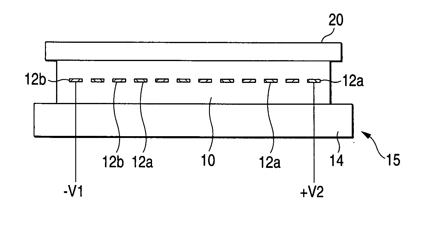
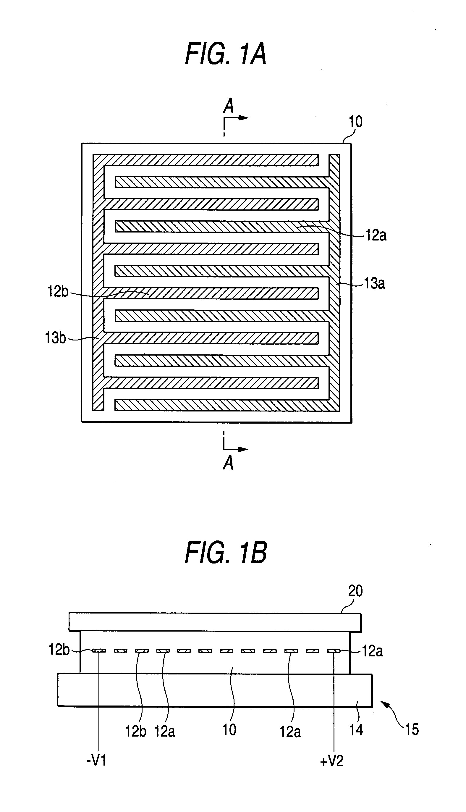
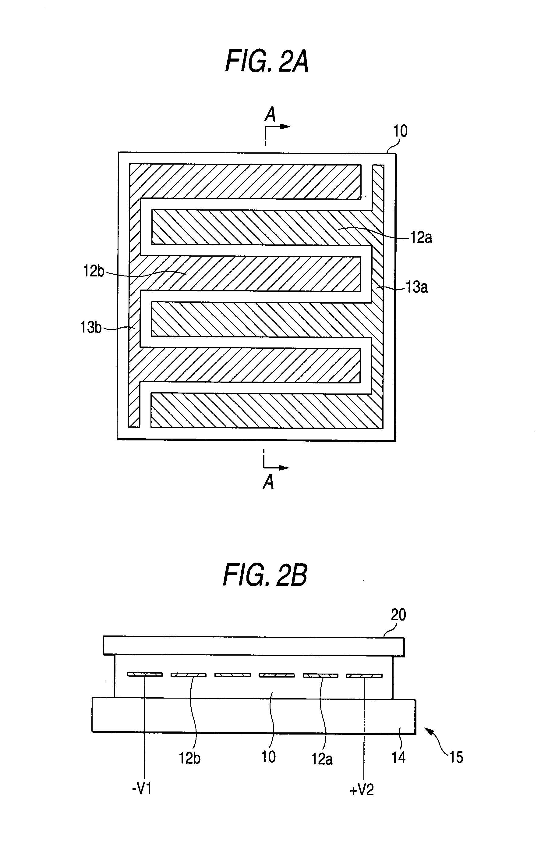
[0035] FIGS. 1 to 3 illustrate examples of electrodes 12a and 12b formed in a chuck body 10 of an electrostatic chuck. All of the electrodes 12a and 12b are formed in a pectinate shape. The positive electrode 12a and the negative electrode 12b are formed in a parallel pattern, and alternately arranged in a direction crossing the electrode pattern (A-A line direction in the figures). The positive electrode 12a are connected to a positive high-voltage power supply through a common connection pattern 13a, and the negative electrode 12b are connected to a negative high-voltage power supply through a common connection pattern 13b.

[0036]FIGS. 1B and 2B illustrate that the electrodes 12a and 12b are formed in the inner layer of the chuck body 10 formed of a ceramic substrate (dielectric layer) and are each connected to the pos...


PUM


Abstract

An electrostatic chuck 15 for chucking and supporting a work 20 made of an electrical insulating material includes a chuck body having a positive electrode 12a and a negative electrode 12b formed therein to which positive and negative voltages are applied. An area ratio of the positive electrode 12a and the negative electrode 12b to a chucking surface of the chuck body is in the range of 60% to 90%.

Description

BACKGROUND OF THE INVENTION [0001] The present invention relates to an electrostatic chuck, and more particularly to, an electrostatic chuck which chucks and supports a work made of an electrical insulating material such as a glass substrate used for a LCD panel. [0002] In apparatuses for processing a semiconductor wafer and the like, an electrostatic chuck has been widely used as a delivery mechanism for chucking and supporting a work, and recently used to deliver an insulating material such as a liquid crystal panel. The mechanisms which generates a chucking force chucking and supporting the work by the electrostatic chuck is known to use (1) a Coulomb force acting between the work and the electrostatic chuck, (2) a Johnson Rahbeck force occurring at a contact interface between the work and the electrostatic chuck, and (3) a gradient force resulting from a non-uniform electric field generated between the work and the electrostatic chuck by the electrostatic chuck. [0003]FIGS. 10A ...

Claims


Application Information

Patent Timeline
IPC IPC(8): H01L21/683B23B5/22
CPCY10T279/23H01L21/6831H01L21/687
Inventor YONEKURA, HIROSHITAMAGAWA, KOKIKOBAYASHI, TAKESHIKANEKO, HITOSHI
Owner SHINKO ELECTRIC IND CO LTD
Learn More