
Meat mincing machine

a mincing machine and meat technology, applied in the field of meat mincing machines, can solve the problems of inaccuracy of portion weight and weight, and achieve the effect of facilitating the continuous determination of the drawn-off amoun

Active Publication Date: 2008-02-14
ALBERT HANDTMANN MASCHFABRICK
View PDF2 Cites 13 Cited by
  • Summary
  • Abstract
  • Description
  • Claims
  • Application Information

AI Technical Summary

Benefits of technology

[0009] It is therefore the object of the disclosure to provide a meat mincing machine and a method, which facilitate the separation of hard parts and however facilitate a high weight accuracy of the portions produced.
[0010] Due to the fact that according to the disclosure a device for determining the discarded amount of hard constituents, i.e. of the amount of separated product, is provided, it can be determined which quantity, i.e. which volume or which mass, is discharged in a certain time period by the meat mincing machine, not as for example minced meat, but rather separated by the separating device and drawn off. The determination of the amount of separated product or of the temporal progression of the separated product facilitates correcting intervention in the production process and compensation of this missing volume, for example by increasing the volume flow fed to the meat mincing machine. The term “determine” is taken to mean the acquisition of the quantity, irrespective of whether it is by measurement or the specific control of the amount of product to be separated.
[0012] The addition of the separated volume for the weight compensation facilitates the production of portions with accurate weight. Thus it is possible to reliably remove hard and solid constituents, such as for example tendons, sinews, rind, bone fragments, connective tissue as well as non-meat constituents, such as for example metal parts and clips, from the soft meat. This means that weight variations can be compensated or at least reduced to a minimum.
[0014] According to a preferred embodiment the device for determining the drawn-off amount of separated product has a conveying device which is arranged at the outlet or in a discharge pipe of the separating device. The conveying device can for example be driven by a motor, wherein then the amount conveyed by the conveying device corresponds to the drawn-off amount of hard constituents. This means that for example the volume separated in a certain time period can be determined using the rotated angle of the conveying device and the amount taken in by the conveying device. A driven conveying device of this nature facilitates a driven and controlled drawing off of the separated product with blockages and constrictions being prevented.
[0022] Preferably, the meat mincing machine comprises at least one sensor, which supplies a signal to a controller in dependence of the composition of the separated product or of the minced foodstuff, the said controller controlling the conveying device or the controlled brake in dependence of the signal. Preferably, the sensor is a colour sensor, which in particular determines the red or white proportion of the separated product or minced foodstuff. The setting of the amount of separated product occurs on the basis of the color of the separated product. With a high red proportion of the separated product it contains too much valuable muscular meat, i.e. too much is being separated. If the separated product is only white, there is the risk that not sufficient hard parts are being separated and for example too much connective tissue is being discharged in the finished portions or the final perforated disc becomes blocked. It must therefore be ensured that a certain proportion of meat is contained in the separated product which can be detected by its color. The sensors enable the conveying device to deliver an appropriate amount of separated product.
[0026] The method according to the disclosure facilitates the continuous determination of the drawn-off amount during the process, so that corrective intervention in the process is possible at any time and without temporal delay.

Problems solved by technology

All these separating devices have the disadvantage that due to the separated material, inaccuracies in the weight of the portions occur with mincing machines in which the minced meat is filled directly into the casing from the mincing machine.
These weight inaccuracies also occur with mincing systems with which portions of minced meat are produced for immediate insertion into packaging machines.

Method used


Image

  • Meat mincing machine
  • Meat mincing machine
  • Meat mincing machine

Examples


Embodiment Construction

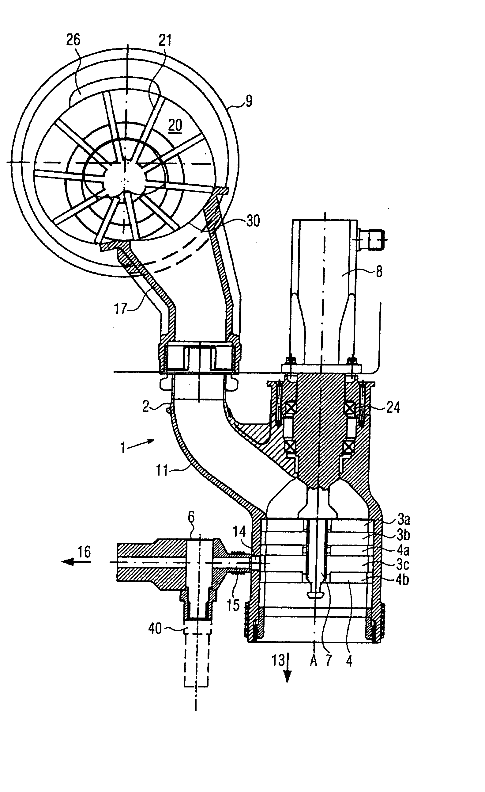
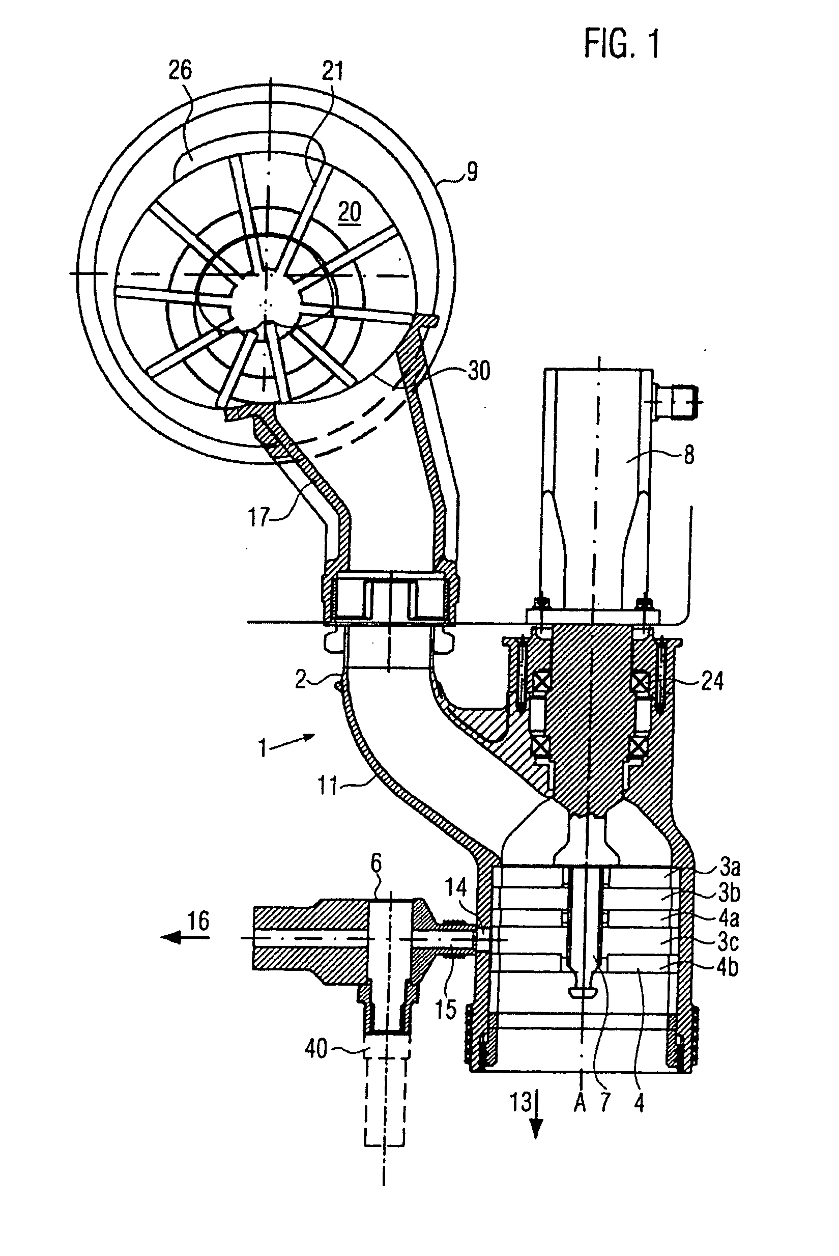
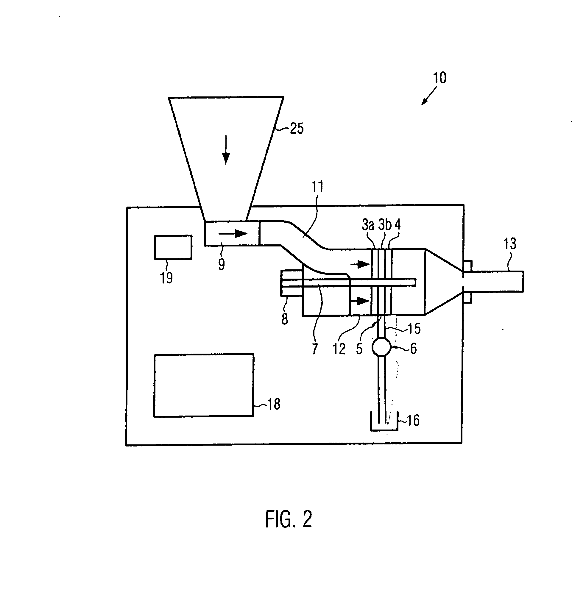
[0036]FIG. 1 shows a cross-section through a possible embodiment of a meat mincing machine 1 according to the disclosure. FIG. 2 shows schematically a longitudinal section through the filling mincer 10, which comprises a meat mincing machine 1 according to the disclosure.

[0037] As can be seen from FIG. 2, here the meat mincing machine 1 is integrated into a filling mincer 10. The reference numeral 25 designates a filling hopper through which coarsely chopped foodstuff, here coarsely chopped meat, is fed to the meat mincing machine 1. Connected to the filling hopper 25, a conveying mechanism 9 is provided, for example the vane pump 9 illustrated in FIG. 1, which conveys the meat to be minced at a certain conveying rate, i.e. a certain volume flow, to the set of cutters 3, 4. Instead of the vane pump 9 also other pumps, feed screws, etc. can of course be used. The vane pump illustrated in FIG. 1 is already known from the state of the art (for example from EP 04 323 88 B2 and EP 10 40...


PUM


Abstract

A meat mincing machine and a method of producing minced foodstuffs, in particular minced meat, with an inlet, at least one blade on a following perforated disc, as well as with a separating device for separating and drawing off hard constituents wherein, to improve the weight accuracy, it has a device for the determination of the drawn-off amount of separated product.

Description

CROSS-REFERENCE TO RELATED APPLICATION [0001] The present application claims the benefit of priority of European Patent Application No. 06 016 258.3 filed Aug. 3, 2006. The entire text of the priority application is incorporated herein by reference in its entirety. FIELD OF THE DISCLOSURE [0002] The disclosure relates to a meat mincing machine and a method of mincing foodstuffs, in particular for the production of minced meat BACKGROUND OF THE DISCLOSURE [0003] A meat mincing machine and a method of this nature are already known from the publication DE 10312605 A1. This publication describes a meat mincing machine for the production of minced foodstuffs with at least one blade and a following perforated disc and a separating device. In the publication an externally driven discharge screw is arranged in a discharge tube. This discharge screw is used to facilitate the quality-compatible mincing and sorting of raw materials independently of the ram pressure. The screw is externally dri...

Claims


Application Information

Patent Timeline
IPC IPC(8): B02C18/36
CPCA22C17/0026B02C2018/308B02C18/305
Inventor SCHMID, KLAUSREUTTER, SIEGFRIEDBAECHTLE, MANFREDBRAIG, WOLFGANG
Owner ALBERT HANDTMANN MASCHFABRICK
Learn More