Eureka AIR delivers breakthrough ideas for toughest innovation challenges, trusted by R&D personnel around the world.

Contact tip and assembly

a technology of contact tip and assembly, which is applied in the field of contact tip and contact tip assembly, can solve the problems of increasing the density of current flowing from the contact tip to the wire electrode, increasing the electrical erosion of the contact tip, and negatively affecting the useful life of the contact tip

Inactive Publication Date: 2008-02-14
ILLINOIS TOOL WORKS INC
View PDF38 Cites 43 Cited by
  • Summary
  • Abstract
  • Description
  • Claims
  • Application Information

AI Technical Summary

Benefits of technology

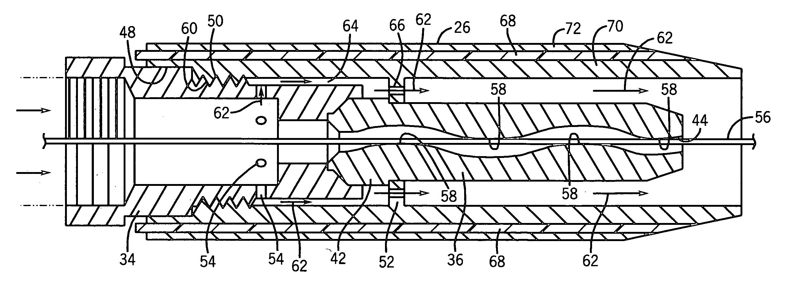
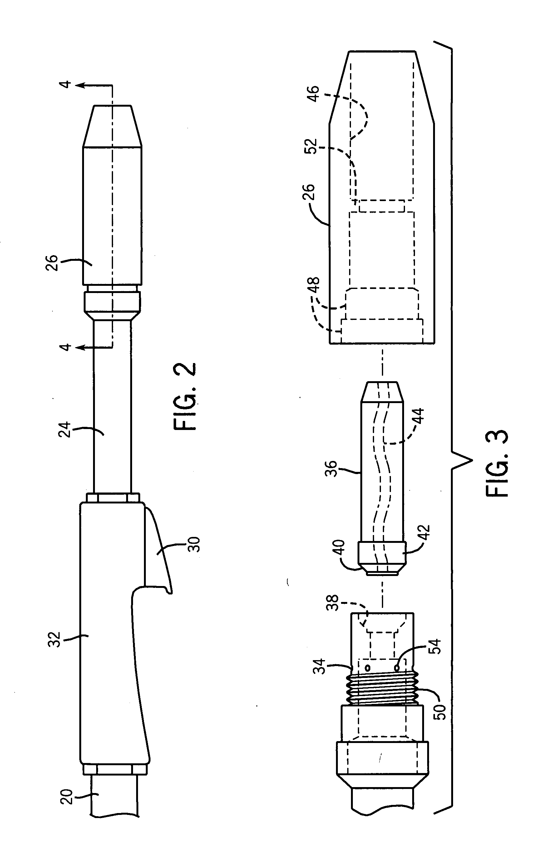
[0007]As discussed in detail below, certain embodiments of the present invention may provide a contact tip that includes a non-linear passage for receiving a wire electrode. The non-linear passage may reduce current density passing to the wire electrode, increase the useful operating life of the contact tip, and increase the reliability of welding systems employing such contact tips. In such embodiments, the contact tip includes a non-linear path that may vary in either two-dimensions or three-dimensions, and both the contact tip and the non-linear path may be formed through various techniques. For instance, in one embodiment, the contact tip may be formed of two mating pieces that have complimentary channels that define a non-linear wire path when the pieces are assembled. However, in other embodiments, a contact tip having a non-linear path may be composed of a single, unitary body or more than two mating pieces. In another embodiment, the non-linear wire path may be formed through application of a force, such as that provided by a rolling process, to the exterior of a contact tip in order to alter a linear path into a non-linear path. In other embodiments, a contact tip assembly is provided for securing a contact tip, which may have a linear or non-linear wire path, by applying a radial clamping force to the contact tip.

Problems solved by technology

Unfortunately, such a design may result in minimal contact between the wire electrode and the contact tip, which increases the density of current flowing from the contact tip to the wire electrode.
In some cases, these disadvantageous effects may result in inconsistent starting of a welding torch, melting of the wire electrode within the contact tip itself, and increased electrical erosion of the contact tip.
As a result, these effects may negatively impact the useful life of the contact tip and require more frequent maintenance or replacement than other components of the welding system.

Method used


Image

  • Contact tip and assembly
  • Contact tip and assembly
  • Contact tip and assembly

Examples


Embodiment Construction

[0017]One or more exemplary embodiments of the present invention will be described below. In an effort to provide a concise description of these embodiments, not all features of an actual implementation are described in the specification. It should be appreciated that in the development of any such actual implementation, as in any engineering or design project, numerous implementation-specific decisions must be made to achieve the developers' specific goals, such as compliance with system-related and business-related constraints, which may vary from one implementation to another. Moreover, it should be appreciated that such a development effort might be complex and time consuming, but would nevertheless be a routine undertaking of design, fabrication, and manufacture for those of ordinary skill having the benefit of this disclosure.

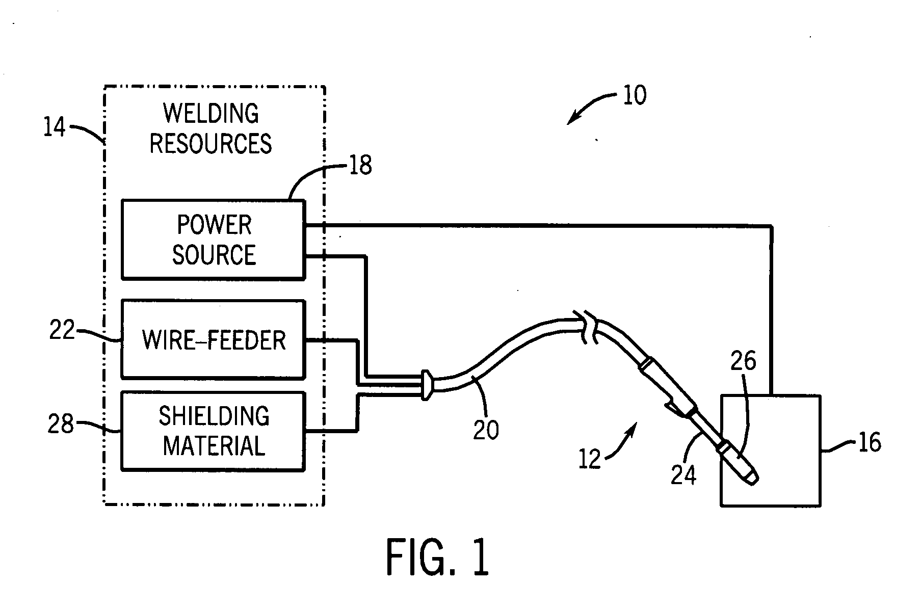
[0018]FIG. 1 illustrates an exemplary wire-feed welding system 10 that incorporates a contact tip having a non-linear electrode path, as described in gre...


PUM

PropertyMeasurementUnit
Forceaaaaaaaaaa
Electrical conductivityaaaaaaaaaa
Dimensionaaaaaaaaaa

Abstract

A contact tip for a welding torch is provided. In one embodiment, the contact tip includes a body formed of an electrically conductive material and a non-linear passage that extends through the body. The non-linear passage of this embodiment is configured to receive a wire electrode and to facilitate electrical communication between the body and the wire electrode. Various contact tip assemblies and manufacturing techniques for forming contact tips are also provided.

Description

CROSS-REFERENCE TO RELATED APPLICATIONS[0001]This application claims priority to U.S. Provisional Patent Application No. 60 / 837,253, entitled “CONTACT TIP AND ASSEMBLY”, filed on Aug. 11, 2006.BACKGROUND[0002]The present invention relates generally to welding systems and, particularly, to contact tips and contact tip assemblies of such systems.[0003]A common metal welding technique employs the heat generated by electrical arcing to transition a portion of a workpiece to a molten state, and the addition of filler metal from a wire or electrode. One technique that employs this arcing principle is wire-feed welding. At its essence, wire-feed welding involves routing welding current from a power source into an electrode that is brought into close proximity or contact with the workpiece. When the electrode is sufficiently close to or touching the workpiece, current arcs from the electrode to the workpiece, completing a circuit and generating sufficient heat to melt and weld the workpiece...

Claims


Application Information

Patent Timeline
IPC IPC(8): B23K9/28
CPCB23K9/123B23K9/325B23K9/173
Inventor HUTCHISON, RICHARD M.
Owner ILLINOIS TOOL WORKS INC
Why Eureka
Eureka Blog
Learn More