Clockwise and counterclockwise rotation switching device for power tool
A technology of electric tools and switching devices, which is applied in the direction of electromechanical devices, portable motorized devices, manufacturing tools, etc., can solve the problems of contact pressure reduction, achieve the effects of improving contact life, suppressing vibration and welding, and avoiding cost increases
- Summary
- Abstract
- Description
- Claims
- Application Information
AI Technical Summary
Problems solved by technology
Method used
Image
Examples
no. 1 approach
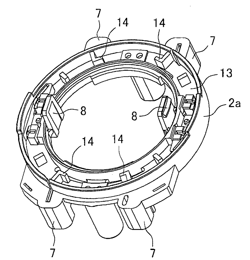
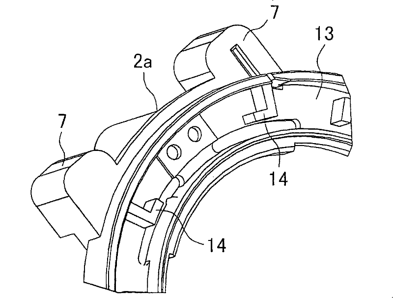
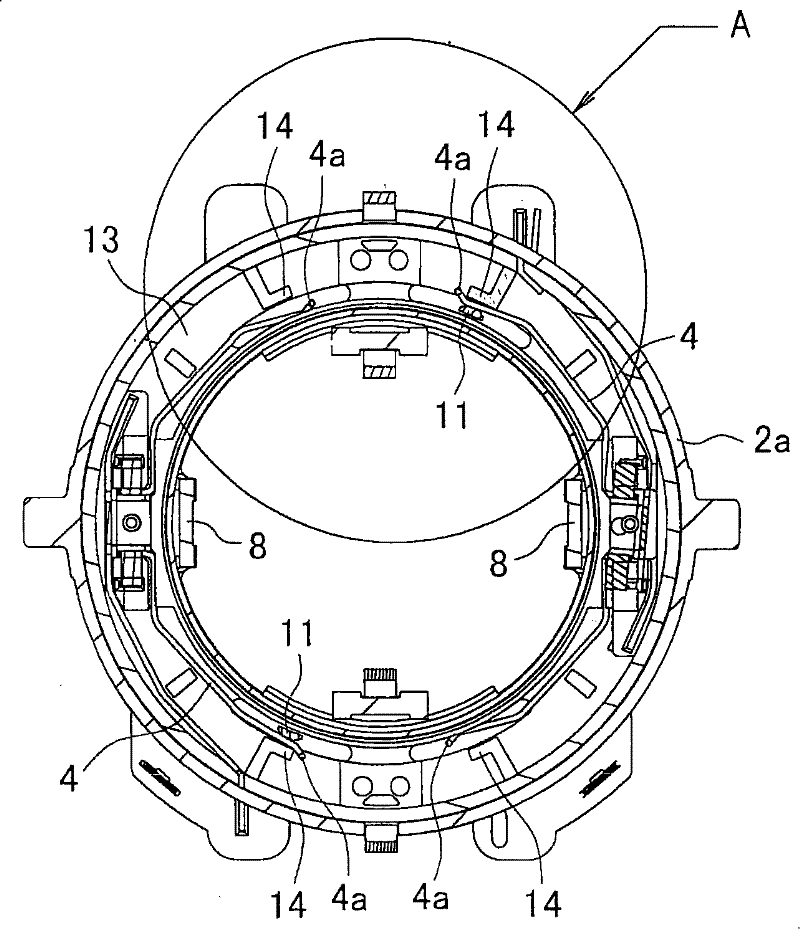
[0024] Figure 1A and Figure 1B It is an explanatory diagram of the component base (the state in which the fixed contact is not attached) 2a used in the forward and reverse switching device of the present invention, Figure 1A represents a stereogram, Figure 1B Indicates a partial enlarged view. Figure 2A and Figure 2B It is an explanatory diagram of the member base 2a in the state where the fixed contact is attached, Figure 2A for a top view, Figure 2B Enlarged image of Part A. In this member base 2a, a pair of fixed contacts 4 and 4 having a point-symmetric plane arc-shaped main structure and the Image 6 , Figure 7 , Figure 8A and Figure 8B The member base 2 described in the above is the same, but on the bottom plate 13 of the member base 2a of the present invention, an L-shaped restriction portion in plan view is integrally protruded on the outer peripheral side of each elastic end 4a of the fixed contact 4 The limiting protrusion 14. When the movable co...
no. 2 approach
[0028] Figure 3A and Figure 3B It is also an explanatory diagram of the member base 2b in a state where the fixed contact is not attached, Figure 3A represents a stereogram, Figure 3BIndicates a partial enlarged view. In this member base 2b, a through hole 15 is provided at the front end position of the restricting projection 14 on the bottom plate 13, and the front end of the restricting projection 14 is provided with elasticity.
[0029] Therefore, by the forward / reverse switching device, the brush base 3 is rotated to the forward rotation position, the movable contact 11 is brought into contact with the elastic end 4a of the fixed contact 4, and the elastic end 4a is flexibly deformed to the outer peripheral side to contact the restricting protrusion 14 abutment, at this time, as Figure 4 As shown, the lower end of the restricting protrusion 14 is flexibly deformed to the outer peripheral side due to its elasticity, and pushes the elastic end 4a toward the movable ...
PUM
 Abstract
Description
Claims
Application Information
 - R&D
- Intellectual Property
- Life Sciences
- Materials
- Tech Scout
- Unparalleled Data Quality
- Higher Quality Content
- 60% Fewer Hallucinations
Browse by: Latest US Patents, China's latest patents, Technical Efficacy Thesaurus, Application Domain, Technology Topic, Popular Technical Reports.
© 2025 PatSnap. All rights reserved.Legal|Privacy policy|Modern Slavery Act Transparency Statement|Sitemap|About US| Contact US: help@patsnap.com


