Dual panel system for controlling the passage of light through architectural structures

Active Publication Date: 2008-02-14
CPI DAYLIGHTING
View PDF42 Cites 24 Cited by
  • Summary
  • Abstract
  • Description
  • Claims
  • Application Information

AI Technical Summary

Benefits of technology

[0012] It is one objective of this invention to provide a transparent / translucent panel unit in which the transmission of light across the system can be adjusted from almost full transparency or translucency to near total opacity while avoiding binding due to flexure or deflection and possible permanent deformation of the unit due to wind, snow and ice loads or due to differential expansion of the panels or sheet that comprise the panel unit. This is accomplished in an elegant manner which does not limit flexure or deflection as in the conventional approaches, but instead modifies or adapts contact surfaces to minimize friction and abrasion and adjusts system parameters to alleviate interference due to flexure and deflection.
[0014] Once installed, the light-controlling members as well as other components housed between the panels can be readily accessed by removing one of the two parallel panels, leaving the second panel in place to protect areas enclosed by the panel system from exposure to the outside environment. Additionally, in one preferred embodiment of the invention, the light-controlling members may be positioned in abutting relationship to maximize the effectiveness of the system in blocking incoming light when the panel system is in the fully closed position.
[0015] Rotation of the light-controlling members may be by the application of rotary motion at one end (or less preferably at both ends) of each light-controlling member. The rotary motion may be applied to a plurality of the light-controlling members directly, as described, for example, in the '255 patent, or it may be applied indirectly. Thus, in one particularly important aspect of the invention, circular engagement surfaces are provided on adjacent light-controlling members. This enables the plurality of light-controlling members within a panel unit to be rotated by imparting rotary motion either manually or with a motorized drive to at least one of the light-controlling members which transmits the rotary motion indirectly across the contacting engagement surfaces of adjacent light-controlling members to rotate the light-blocking surfaces and vary the level of light passing through the panel unit. Also, the use of two spaced-apart panels (rather than a unitary panel as in the '255 patent) makes it possible to house some or substantially all of the drive mechanism between the panels and thus within the panel unit, out of the way of other structural components.
[0017] The panel units of the present invention can maintain a perfect balance between light transmission and thermal performance, fostering a daylighted, comforting, livable and productive environment all year long without concern over flexure or deflection and possible permanent deformation of the panel units of the system. They also conserves energy on peak demand. The panel units may be fully automatic, with built-in intelligent light controllers and an embedded program that senses the daylight outside and manages the level of light and solar heat gain inside based on the level of sunlight outside. This will enable users to control natural daylight and comfort levels in any space all day long, and all year long, simply by setting desired light levels.

Problems solved by technology

The known approaches to controlling the amount of light admitted through glazing systems, however, are limited and are generally difficult or expensive to construct and service.
Prior approaches to controlling the level of light passing through architectural structures have been of only limited usefulness.
Furthermore, louver blinds are difficult and expensive to assemble, apply, operate, maintain and replace, and cannot be readily adapted for use in non-vertical applications or in applications in which it is either desirable or necessary to control the flexible members from only one end.
Also, if a tubular member fails, the entire panel must be removed and replaced.
This may be prohibitively complex and expensive in certain applications.
Where the panels are part of a protected enclosure, removal of an entire panel will expose the interior of the enclosure to the exterior environment which can be particularly problematic.
Additionally, in the design of the '255 patent the diameter of the radiation blocking members is constrained by the size of the cells—where circumstances make larger or smaller radiation-blocking members desirable or necessary due to economic or other reasons, the system of the '255 patent cannot accommodate them.
This is a very complex and expensive design which could be made substantially simpler and less expensive if the same result could be achieved with fewer larger diameter radiation-blocking members or with simpler drive mechanisms that preferably could be substantially contained within the area defined by the panel.
Furthermore, the unitary cellular panel structure of the '255 patent resists bending, making it difficult to use the system in architectural applications where tight radius bends are required.
Additionally, the cellular-panel structure has insulation, soundproofing and structural limitations arising from its maximum 30 mm thickness or depth that make its use less than ideal in applications calling for high insulation values, substantial soundproofing or long span construction.
Finally, the unitary cellular panel structure of the '255 patent does not permit the use of different combinations of interior and exterior panel colors and finishes as required or desirable in many architectural applications.
These prior approaches, however, have a number of drawbacks.
While certainly less problematic, there are also structural and assembly challenges in respect of the alignment of the elongated light-controlling members and carriage member scallops in the panel system of the '255 patent.
However, perhaps more importantly, such systems may in certain environments encounter loads due to high winds and ice and snow which cause the panel systems to flex or deflect and even permanently deform.
Also, temperature differentials between outer panel members that are exposed to varying outdoor temperatures and inner panels that are exposed to varying indoor temperatures may cause flexure or deflection and possibly permanent deformation.
These cross-members also typically must be made of a rigid material like extruded aluminum which blocks light transmission and therefore is aesthetically undesirable.

Method used


Image

  • Dual panel system for controlling the passage of light through architectural structures
  • Dual panel system for controlling the passage of light through architectural structures
  • Dual panel system for controlling the passage of light through architectural structures

Examples


Embodiment Construction

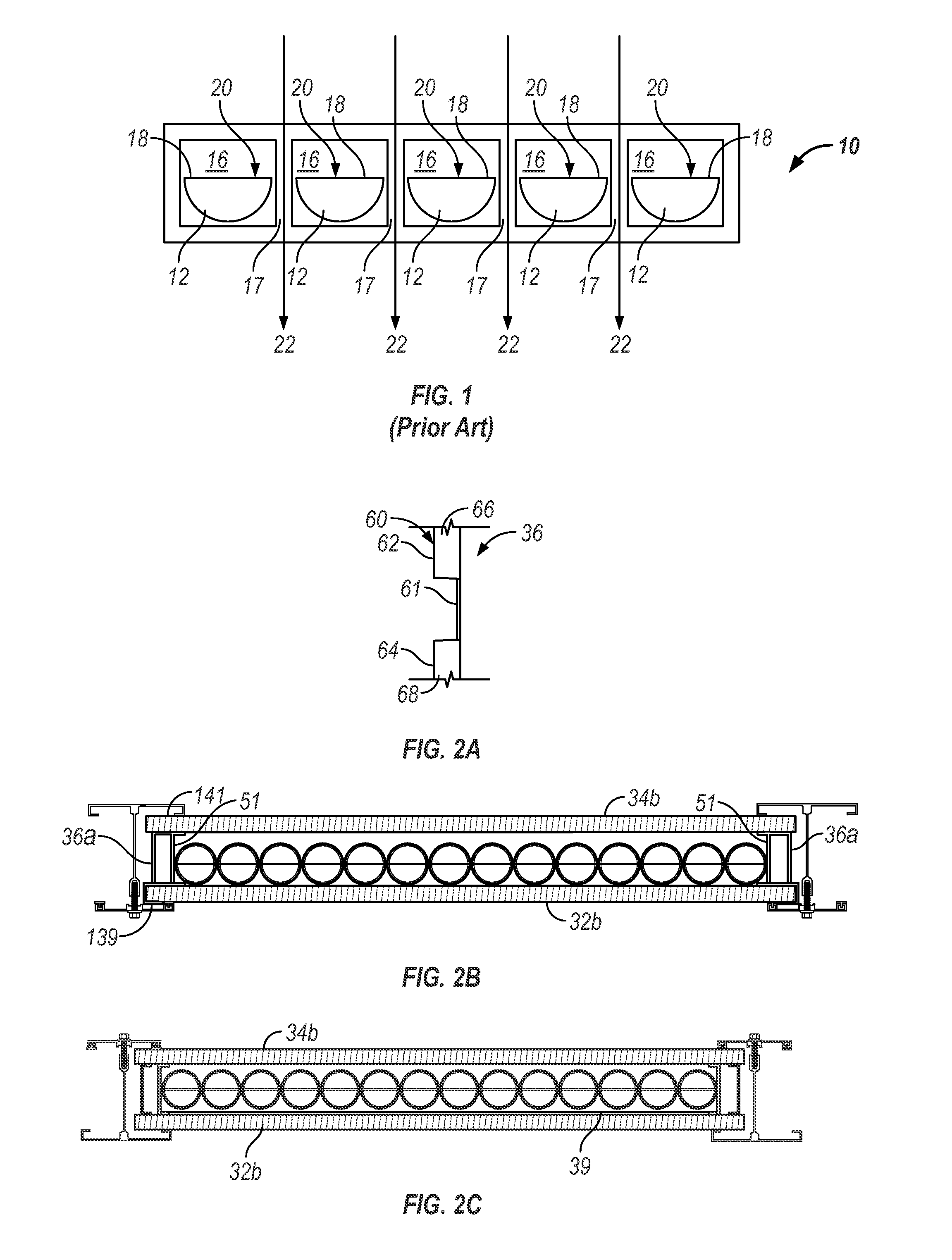
[0049] Turning first to FIG. 1, an elevational view of a transparent or translucent panel 10 in accordance with the teaching of prior U.S. Pat. No. 6,499,255 is shown. Panel 10 includes a series of half-cylinder louvers 12 rotatably mounted in a series of adjacent, segregated cells 16 separated by walls 17. Louvers 12 each have an opaque top surface 18. Thus, in the illustrated embodiment where the louvers are in the fully closed position, light rays 20 strike opaque surfaces 18, which block light transmission through the louvers. Unfortunately, the transparent or translucent material in the walls 17 between adjacent cells remains unblocked, which means that light rays 22 will penetrate the panel through these walls. Thus, even with all of the louvers in the fully closed position, the panels of the '255 patent admit light: in one commercial embodiment of this invention, the panels have been found to admit a minimum of about 6% light transmission. Also, the panel of the '255 patent c...


PUM


Abstract

The invention comprises improvements to transparent / translucent panel systems including two spaced flat panels and a series of elongated, abutting, rotatably mounted transparent / translucent light-controlling members disposed between the panels in which the light-controlling members are at least partially tubular or have annular members along their length to facilitate rotation of the light-controlling members and include a light-blocking surface including improvements to ensure continued efficient operation when the panel systems are subjected to flexure or deflection and possible permanent deformation.

Description

[0001] This application is a continuation-in-part of U.S. patent application Ser. No. 10 / 600,261, filed Jun. 20, 2003. The entire disclosure of the foregoing patent application is hereby incorporated by reference.FIELD OF THE INVENTION [0002] This invention relates to transparent / translucent panel systems for controlling the level of light admitted through sloped glazing, skylights, roofs, walls, and other architectural structures designed to pass light and, more particularly, to improvements in the structure of such systems to ensure continued reliable operation when the panel systems are subjected to flexure or deflection due to loading. BACKGROUND OF THE INVENTION [0003] Various types of transparent and translucent glazing systems are available for the construction of sloped glazing, skylights, roofs, walls, and other architectural structures designed to pass light for daylighting interiors and other purposes. When using such glazing systems, it is often desirable to optimize the...

Claims


Application Information

Patent Timeline
IPC IPC(8): E05F15/20A01G9/22A01G9/24E04D3/06E04D13/03E04F10/08E06B7/096E06B9/24H01L31/00H01L31/042
CPCA01G9/22A01G9/243E04D3/06E04D13/033Y02E10/40E06B9/24F24J2/407Y02B10/12Y02B80/50E04F10/08E04F10/10E06B2009/2405F24S50/80Y02B10/10Y02B80/00Y02P60/12Y02P60/14Y02A30/24Y02A40/25
Inventor KONSTANTIN, MOSHE
Owner CPI DAYLIGHTING
Why Eureka
Try Eureka