
Protection device for the floor of a land vehicle

Inactive Publication Date: 2008-02-14
NEXTER SYST SA
View PDF12 Cites 50 Cited by
  • Summary
  • Abstract
  • Description
  • Claims
  • Application Information

AI Technical Summary

Benefits of technology

[0008] The aim of the, invention is to propose a protection device to ensure, with a relatively reduced overall mass, ef

Problems solved by technology

This results in a considerable mass for the armor which prejudices the vehicle's mobility.
It also results in reduced ground clearance.
The architecture is not optimized with regard to the transmission of stresses.

Method used


Image

  • Protection device for the floor of a land vehicle
  • Protection device for the floor of a land vehicle
  • Protection device for the floor of a land vehicle

Examples


Embodiment Construction

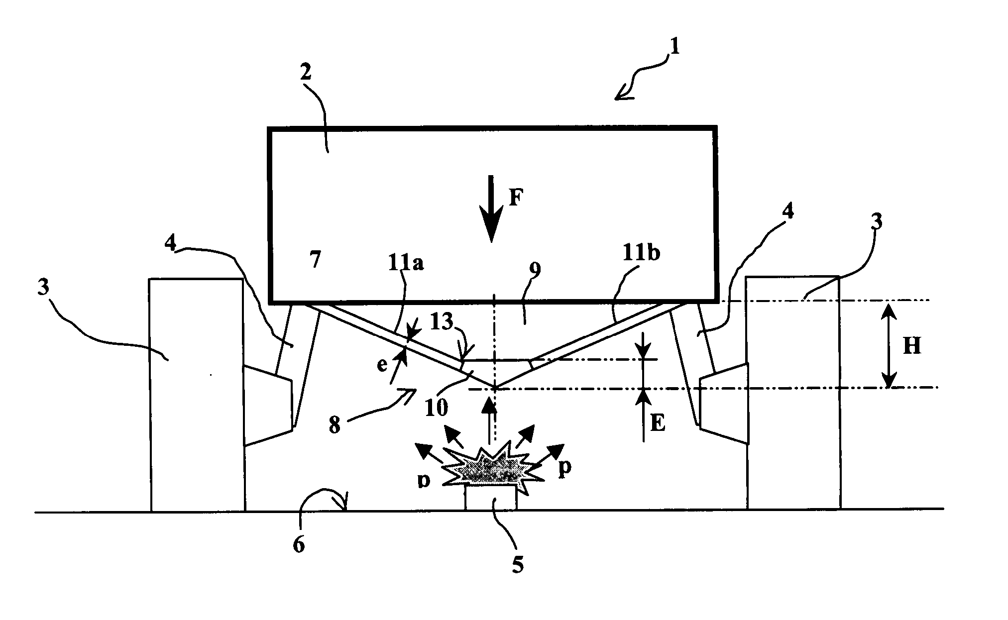
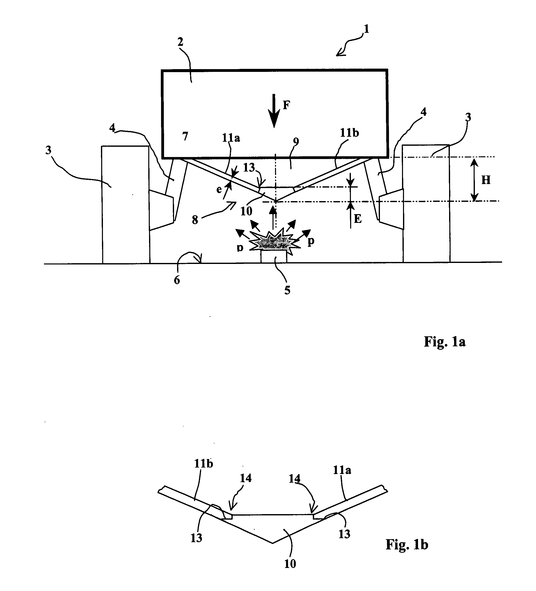
[0024]FIG. 1a shows a vehicle 1 which incorporates a cab 2 carried by wheels 3 connected to the cab by axle arms 4. FIG. 1a shows a blast effect mine positioned on the ground 6. When ignited, this mine generates high pressure (schematized by arrows P) in the direction of the floor 7 of a vehicle 1.

[0025] In accordance with the invention, a device 8 is provided to ensure the protection of the floor 7 (or lower part) of the vehicle.

[0026] The device is shown here in the form of a separate caisson fastened to the lower part of the vehicle 1.

[0027] It is naturally possible, without departing from the scope of the invention, to define a vehicle whose actual structure will incorporate the device 8 incorporated with the cab 2 from the onset. The caisson 8 may thus be incorporated with the floor itself.

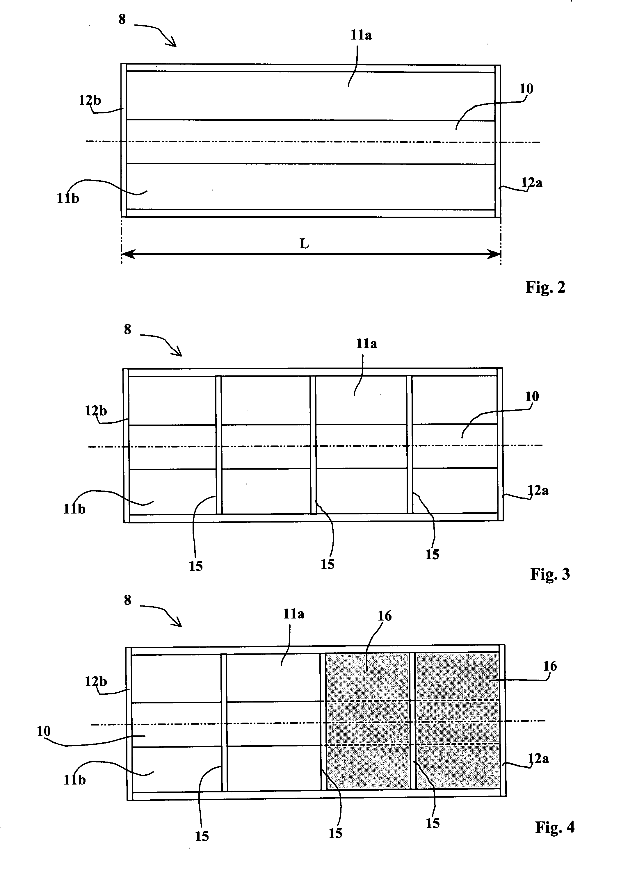
[0028] The caisson 8, within the meaning of the invention, is intended as a structure delimited by walls and which itself delimits an internal volume 9. This structure may be added onto a...


PUM


Abstract

A protection device for the floor of a land vehicle against mines, said device comprising at least one caisson with a convex external surface oriented towards the ground wherein said caisson incorporates a median part arranged between two lateral walls and extending over the full length of said caisson, the median part of said caisson being of a thickness (E) greater than that (e) of said lateral walls and being designed so as to transmit the stress, when a mine detonates, towards said lateral walls.

Description

BACKGROUND OF THE INVENTION [0001] 1. Field of the Invention [0002] The technical scope of the invention is that of devices to ensure the protection of the floor of a land vehicle against mines. [0003] 2. Description of the Related Art [0004] To protect the floor of a land vehicle it is known to position armor under the floor so as to absorb and / or deviate the blast produced by the mine. Know armor comprises one or several metallic or composite layers and possibly deflector means. [0005] Patent DE10144208 thus describes armor incorporating a convex caisson covering the vehicle floor. The shape of the caisson ensures the deviation of part of the mine's blast. [0006] These known types of armor or protection devices are usually of constant thickness over the full width to be protected and are defined according to the maximal constraints generated by the mine. This results in a considerable mass for the armor which prejudices the vehicle's mobility. It also results in reduced ground cle...

Claims


Application Information

Patent Timeline
IPC IPC(8): F41H7/02
CPCF41H7/042
Inventor BARBE, YVESBETTENCOURT, BENOITWAGNEZ, LAURENT
Owner NEXTER SYST SA
Learn More