Balance corrector

a technology of balance corrector and disc drive, which is applied in the direction of instruments, structural/machine measurement, material analysis, etc., to prevent the impact applicator from reducing the vibration of the housing, reduce the impact, and reduce the impa

Inactive Publication Date: 2008-02-14
COCHLEAR LIMITED +1
View PDF14 Cites 1 Cited by
  • Summary
  • Abstract
  • Description
  • Claims
  • Application Information

AI Technical Summary

Benefits of technology

[0010]The present invention is directed to an apparatus that can highly precisely correct the imbalance and a manufacturing method of a disc drive.
[0011]An apparatus according to one aspect of the present invention that corrects a weight imbalance around an axis of a spindle motor that rotates a disc in a disc drive includes an impact applicator that applies an impact to a housing that houses the spindle motor and the disc, a plate that supports the housing and impact applicator, a spring member that supports the plate, and enables the plate and the housing to vibrate together when the spindle motor rotates; and a detector that detects a vibration of the housing when the spindle motor rotates. According to this balance corrector, the spring member enables the plate and the housing to vibrate together, and prevents the impact applicator from reducing the housing vibration, maintaining a sufficiently high output or amplitude of the detector. As a result, the output of the detector is less affected by the noise, and the measurement precision improves. Preferably, the spring member has a spring constant k that satisfies ωo≦ωp=√k / m, where m is a total weight supported by the spring member, ωo is a rotating frequency of the spindle motor, and ωp is a resonance frequency of the housing and plate. This condition prevents an attenuation or reduction of the vibration of the spindle motor.
[0012]An apparatus according to another aspect of the present invention that corrects a weight imbalance around an axis of a spindle motor that rotates a disc in a disc drive includes a detector that detects a vibration of the housing when the spindle motor rotates, the detector being provided apart from a housing that houses the spindle motor and the disc. Since the apparatus separates the detector from the housing, the detector is not affected by the impact applied by the housing. In addition, the detection precision of the detector is not affected by the attachment and detachment of the housing. Moreover, in detaching and attaching the housing, the detachment and attachment of the detector are unnecessary, improving the operability.
[0013]An apparatus according to still another aspect of the present invention that corrects a weight imbalance around an axis of a spindle motor that rotates a disc in a disc drive includes an impact applicator that point-contacts and applies an impact to a housing that houses the spindle motor and the disc. According to this balance corrector, the impact applicator point-contacts the housing, and eliminates an alignment that would be otherwise required in the prior art in which they surface-contact each other, thereby improving the operability. The impact applicator can stably apply a predetermined impact force to the housing, improving the imbalance correction precision.
[0014]An apparatus according to still another aspect of the present invention that corrects a weight imbalance around an axis of a spindle motor that rotates a disc in a disc drive includes an impact applicator that applies an impact to a housing that houses the spindle motor and the disc, a detector that detects a vibration of the housing when the spindle motor rotates, and a controller that obtains rotational phase information directly from the spindle motor and a detection result from the detector, and controls an impact force and impact application timing by the impact applicator based on the rotational phase information and detection result. According to this balance corrector, the controller obtains the rotational phase information directly from the spindle motor, and eliminates the conventional optical sensor. In comparison with a conventional mechanical index that obtains the rotational phase information indirectly, the correction precision improves, and the balance corrector can be made small and inexpensive.
[0015]A manufacturing method according to another aspect of the present invention of a disc drive that rotates plural discs using a spindle motor and records information in and reproduces the information from the discs includes the steps of leaning the plural discs to the same side of the spindle motor, and correcting a weight imbalance around an axis of the spindle motor by using the above apparatus. This manufacturing method leans the plural discs to the same side of the spindle motor, and cancels out a difference in frictional force, facilitating the balance correction. The leaning step may incline the plural discs or pushes edges of the discs towards the same direction.

Problems solved by technology

Moreover, in detaching and attaching the housing, the detachment and attachment of the detector are unnecessary, improving the operability.

Method used


Image

  • Balance corrector
  • Balance corrector
  • Balance corrector

Examples


Embodiment Construction

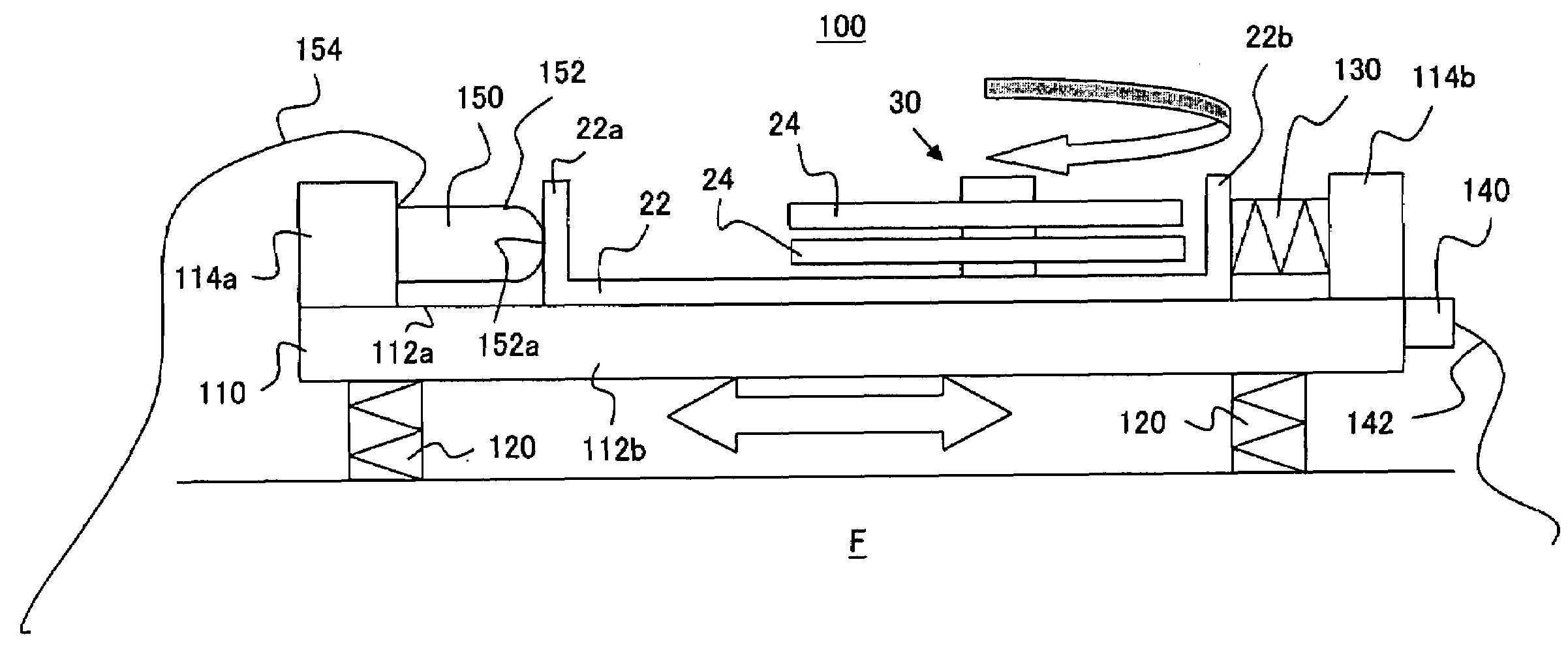
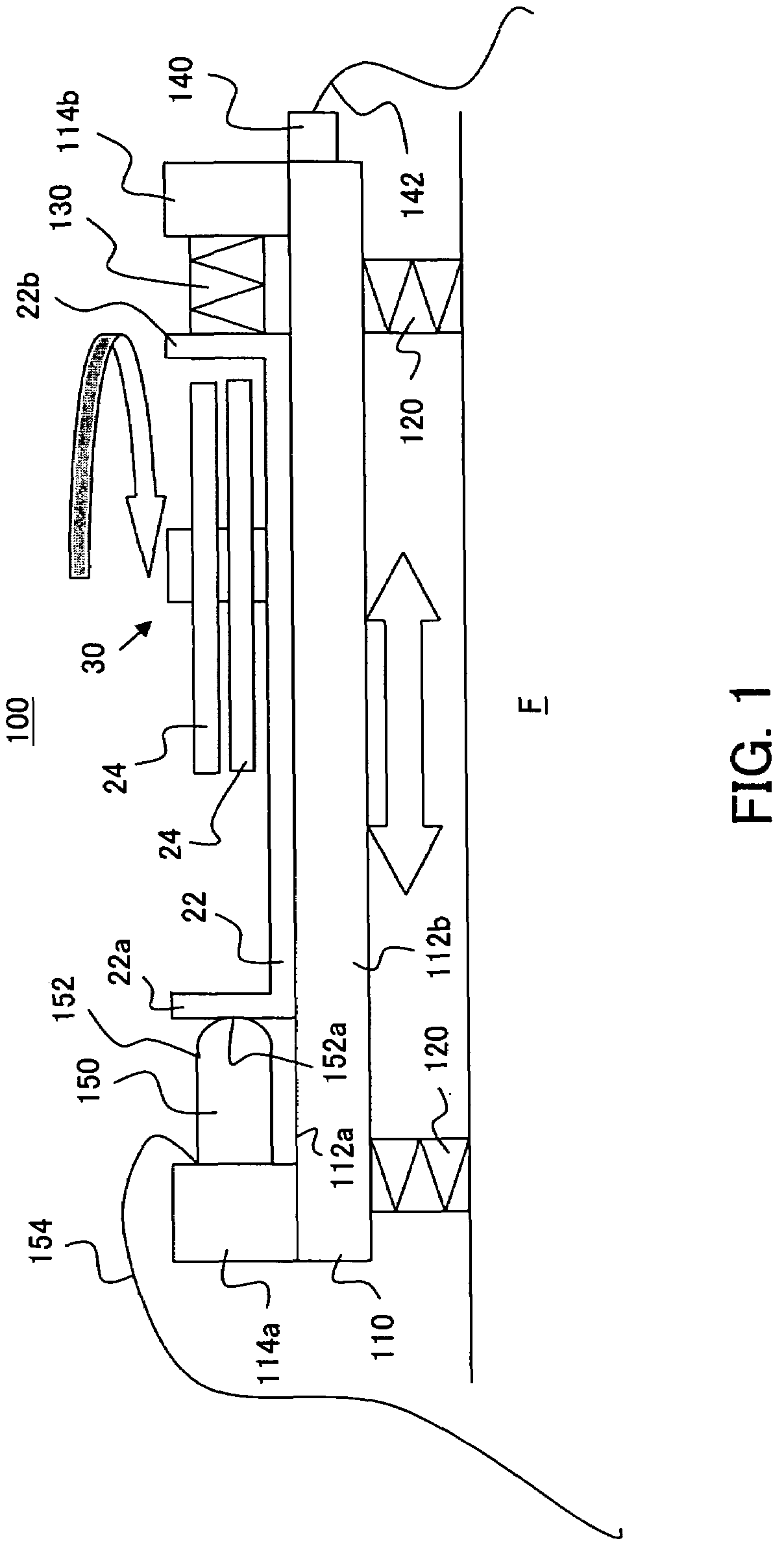
[0030]Referring now to FIG. 1, a balance corrector 100 will be described. Here, FIG. 7 is a schematic sectional view of the balance corrector 100. The balance corrector 100 detects and corrects imbalance so that the imbalance amount falls within a permissible range. The imbalance is recognized as a vibration of a housing (or disc enclosure base) 22 when a pair of discs 24 are rotated with the spindle hub 32 of the spindle motor 30 in the pre-assembled HDD 20. Therefore, the balance corrector 100 detects and corrects the vibration of the housing 22. While this embodiment provides two discs 24, the number of discs 24 is not limited to two.

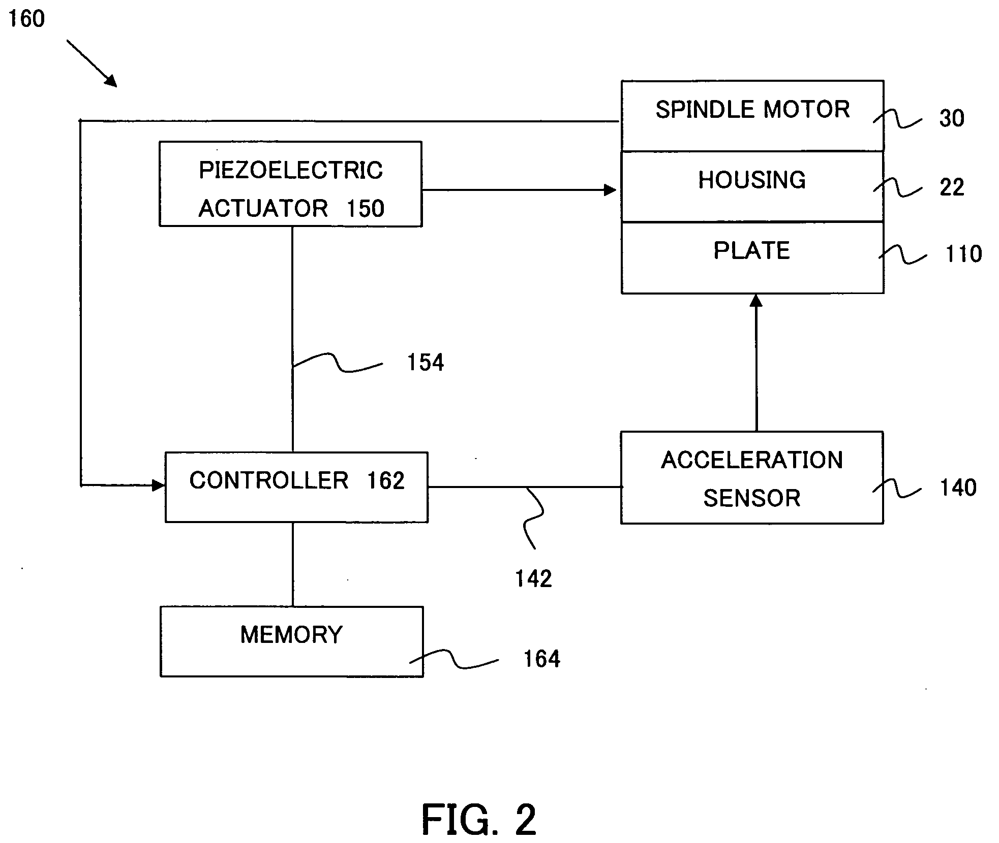
[0031]The balance corrector 100 includes, as shown in FIG. 1, a plate 110, plural spring members 120, a compression spring 130, an acceleration sensor (detector) 140, a piezoelectric actuator 150, and a controller 160 (not shown in FIG. 7).

[0032]The plate 110 is a box member made of a material, such as aluminum and stainless steel, and supports the h...


PUM

PropertyMeasurementUnit
weight imbalanceaaaaaaaaaa
total weightaaaaaaaaaa
rotating frequencyaaaaaaaaaa

Abstract

An apparatus that corrects a weight imbalance around an axis of a spindle motor that rotates a disc in a disc drive includes an impact applicator that applies an impact to a housing that houses the spindle motor and the disc, a plate that supports the housing and impact applicator, a spring member that supports the plate, and enables the plate and the housing to vibrate together when the spindle motor rotates, and a detector that detects a vibration of the housing when the spindle motor rotates.

Description

[0001]This application claims the right of a foreign priority based on Japanese Patent Application No. 2006-220476, filed on Aug. 11, 2006, which is hereby incorporated by reference herein in its entirety as if fully set forth herein.BACKGROUND OF THE INVENTION[0002]The present invention relates generally to an adjustment of driving in a disc drive, and more particularly to an apparatus that corrects weight imbalance (simply referred to as “imbalance” hereinafter) around an axis of the spindle motor. The present invention is suitable, for example, for an apparatus that corrects the disc rotating balance in a hard disc drive (“HDD”).[0003]Along with the recent spread of the Internet etc., a demand for fast recording of a large amount of information is growing. A magnetic disc drive, such as an HDD, is required to have a larger capacity and an improved response. For the larger capacity, the HDD narrows a track pitch on the disc and increases the number of installed discs. For the impr...

Claims


Application Information

Patent Timeline
Patent Type & Authority Applications(United States)
IPC IPC(8): G01N3/30
CPCH02K15/165
Inventor KOHEI, TORUNAKAYAMA, NOBUYOSHIKOTAKE, SHIGEYUKIARUGA, KEIJI
Owner COCHLEAR LIMITED
Why Eureka
Try Eureka