Method and system in connection with permanent magnet synchronous machines

a technology of synchronous machines and permanent magnets, applied in the direction of electronic commutators, motor/generator/converter stoppers, dynamo-electric converter control, etc., can solve the problems of ac motor drives, excessive voltage stress in the stator winding insulation, acoustic noise and power loss, etc., to achieve accurate determination of the speed and position of the rotor

Active Publication Date: 2008-02-07
ABB (SCHWEIZ) AG
View PDF10 Cites 12 Cited by
  • Summary
  • Abstract
  • Description
  • Claims
  • Application Information

AI Technical Summary

Benefits of technology

[0007] The invention is based on the idea that the speed and position of the rotor can be accurately determined even at low speeds by using an adaptive full-order observer in combination with pulsating high-frequency signal injection [9]. The signal injection method can be surprisingly used in connection with an LC output filter, although the LC filter is situated on the current path between the inverter and the permanent magnet synchronous machine.
[0008] By using the method of the invention, the PMSM can be controlled without any speed or position sensors using vector control, thus eliminating the need of mechanical vulnerable instruments and additional wiring. Further, the method does not require any additional voltage or current measurements. Only the voltage of the intermediate circuit of the frequency converter and the output current of the inverter need to be measured. The method of the invention provides accurate information on the rotor position and speed and thus enables accurate control of PMSM drives equipped with an LC filter.

Problems solved by technology

Problems may be encountered in AC motor drives due to the non-sinusoidal voltage produced by a pulse-width modulated (PWM) inverter.
The high rate of change of the voltage (i.e. high du / dt) may cause excessive voltage stresses in the stator winding insulations.
Lower-order harmonics cause acoustic noise and power losses; the losses caused by eddy currents are a special concern in high-speed solid-rotor motors.

Method used


Image

  • Method and system in connection with permanent magnet synchronous machines
  • Method and system in connection with permanent magnet synchronous machines
  • Method and system in connection with permanent magnet synchronous machines

Examples


Embodiment Construction

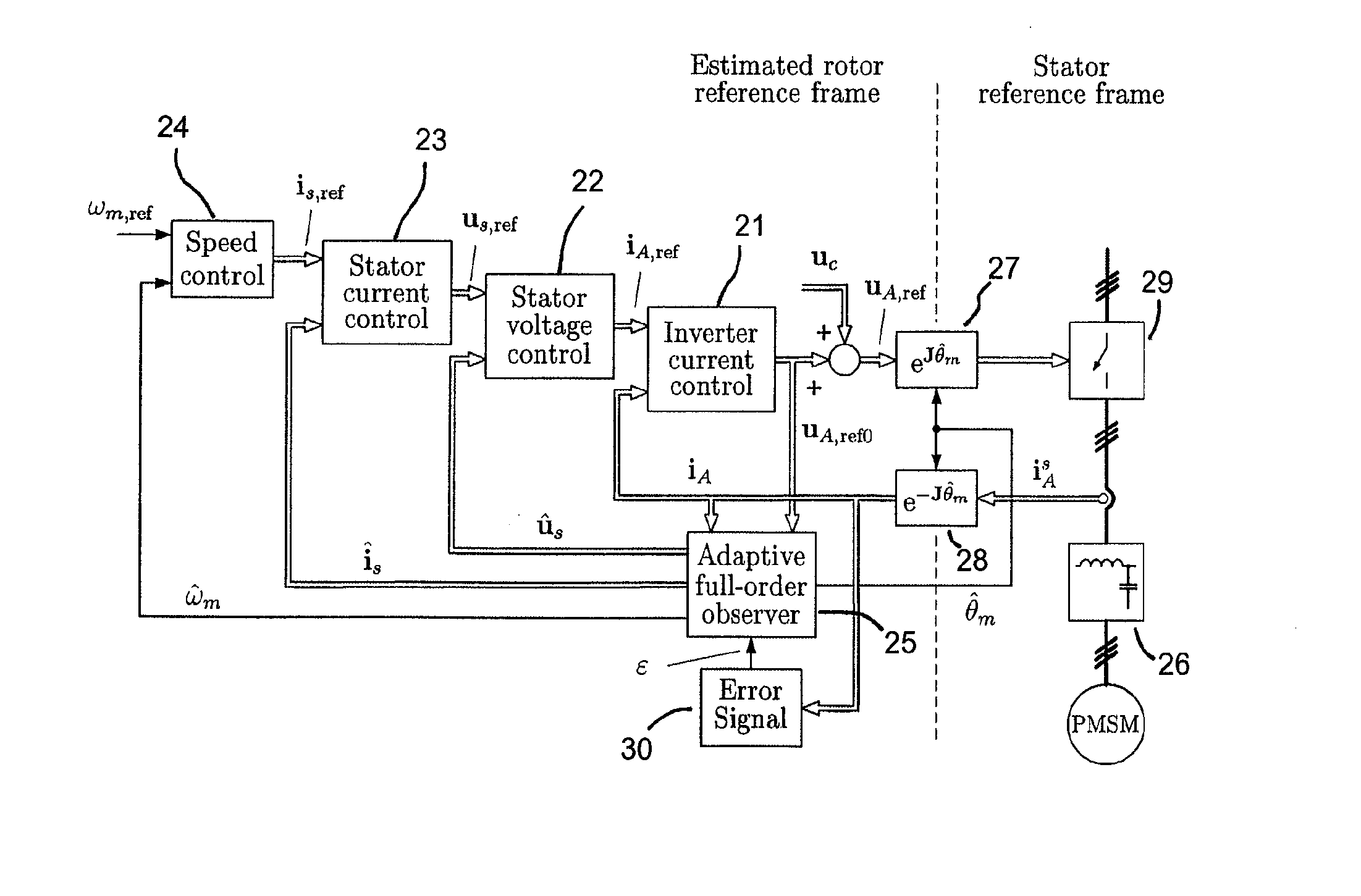
[0014] In the following subsections, first a filter and machine model will be briefly discussed. Then an example of a control system suitable to be used in connection with the invention is described, after which the structure of the speed-adaptive full-order observer and the high-frequency signal injection used in the method of the invention is described.

Filter and Motor Models

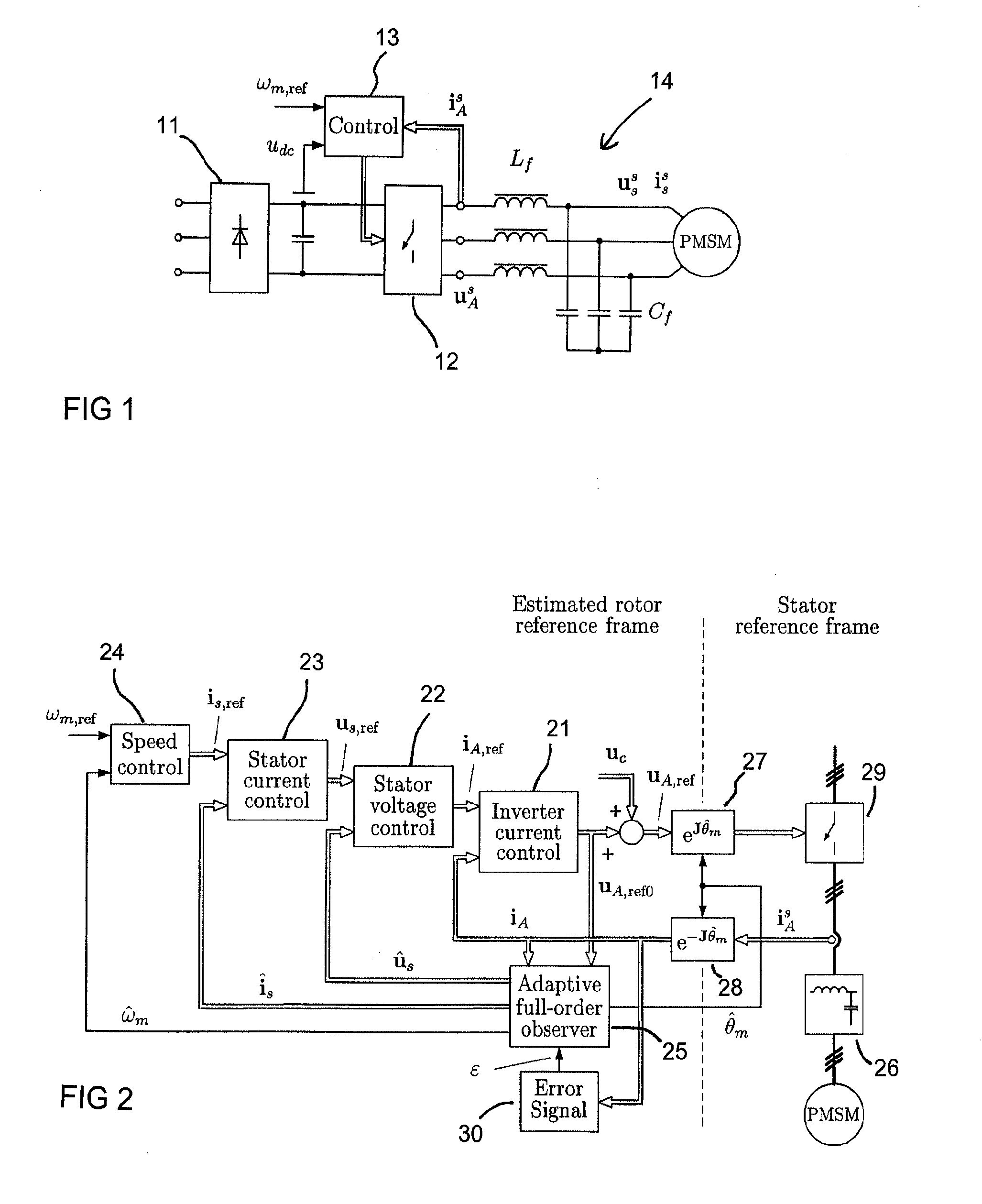
[0015]FIG. 1 shows a PMSM drive system equipped with an LC filter 14. The inverter output voltage uA is filtered by the LC filter consisting of filter inductances Lf and filter capacitances Cf, resulting in a nearly sinusoidal stator voltage us. The inverter output current iA and the dc-link voltage udC are the only measured quantities. The dc-link voltage is used in the control of the inverter itself. The dc-link voltage is formed by using a diode bridge 11 and inverter 12 is used to form alternating voltage from the dc-link voltage. The speed reference signal ωm,ref is given as an input to the control 13 ...


PUM


Abstract

A method and a system in connection with a speed and position sensorless permanent magnet synchronous machine equipped with an output filter (26) and driven by an inverter (29), which method comprises the steps of forming a speed-adaptive full-order observer (25) based on the dynamic model of the combination of the permanent magnet synchronous machine (PMSM) and the output filter (26), measuring the inverter output current (iA), estimating inverter output current (ÎA), determining the estimate for the electrical angular speed ({circumflex over (ω)}m) using the estimated and measured inverter output currents (îA, iA) in an adaptation law, injecting a voltage signal (uc) into the inverter voltage reference (uA,ref 0) to obtain a modified voltage reference (uA,ref), detecting an error signal (ε) from the measured inverter output current (iA), and calculating the speed correction term (ωε) used in the adaptation of the observer from the error signal (ε).

Description

BACKGROUND OF THE INVENTION [0001] The invention relates to a method and system in connection with permanent magnet synchronous machines (PMSM). More specifically, the invention relates to a method of determining the angular speed and the rotor position of a speed and position sensorless PMSM drive equipped with an output filter and to an apparatus for carrying out the method. [0002] Problems may be encountered in AC motor drives due to the non-sinusoidal voltage produced by a pulse-width modulated (PWM) inverter. The high rate of change of the voltage (i.e. high du / dt) may cause excessive voltage stresses in the stator winding insulations. It may also excite the parasitic capacitances of the stator winding and produce bearing currents. Lower-order harmonics cause acoustic noise and power losses; the losses caused by eddy currents are a special concern in high-speed solid-rotor motors. [0003] A common approach to overcome these problems is to use an inverter output filter [1]-[4]. A...

Claims


Application Information

Patent Timeline
IPC IPC(8): H02P6/18
CPCH02P21/0039H02P2207/05H02P2203/11H02P21/0053H02P21/32H02P21/24
Inventor SALOMAKI, JANNEPIIPPO, ANTTI
Owner ABB (SCHWEIZ) AG
Why Eureka
Try Eureka