Slatted device for stable floors

Inactive Publication Date: 2008-02-07
ROTECNA
View PDF9 Cites 6 Cited by
  • Summary
  • Abstract
  • Description
  • Claims
  • Application Information

AI Technical Summary

Benefits of technology

[0006]In fact, thanks to the sliding hinge means, not only can the trap door swing, but it can also be retracted into the pit. Therefore it is much easier to clean the stable compartment floor, because the excrements can be comfortably removed by pushing them inside the pit from any side of the slatted device. Also, the downwards movement of the trap door causes most of the excrements deposited on its surface to also fall into the pit. So it is simpler, more hygienic and quicker to clean the stable compartment floor than in the case of the usual state-of-the-art stable floors.
[0010]As mentioned, another of the problems posed by opening the trap door is the high risk that the mothers' young may fall accidentally into the pit during the cleaning operation. Therefore, preferably the chassis comprises a secondary slat provided below the trap door. In fact, this secondary slat has larger holes than those of the trap door, which the animals walk over. Therefore, the openings of the secondary slat allow the excrements to fall easily into the pit. However, these openings are small enough to prevent any young animals from falling accidentally into the pit.
[0012]The trap door of the device according to the invention can always swing and move with respect to the chassis. However, depending on the position in the pit of the trap door once it is retracted, the amount of excrements that knocks against said trap door will vary. Therefore, preferably, the inner pivots are provided near a first end of the frame. This way the trap door in its retracted position interferes as little as possible, therefore allowing the stable compartment floor to be cleaned comfortably. Also, it prevents the trap door from getting excessively dirty.
[0013]In order to facilitate the cleaning of the stable compartment as much as possible, it is desirable that the pit hole be as large as possible and that at the same time, the trap door, in its retracted position, interferes as little as possible with the excrements falling into the pit. Consequently, preferably, the frame is rectangular and the inner pivots are provided on the longer faces of said frame. Therefore, in this advantageous arrangement the pit inlet hole, in the longitudinal direction, is completely free. This makes it considerably easier to remove the excrements and significantly reduces the amount of excrements that knocks against the top surface of the trap door as it falls, thereby improving the cleaning of the stable compartment floor.
[0014]If the joining elements between the trap door and the chassis are, for example, screws, it may be difficult to remove the trap door because the dried excrements on these joining elements cause premature rusting that makes it difficult to remove the trap door. So, preferably the side guides of the trap door are open at one end. This means that the sliding hinge means do not have any joining elements that need to be removed using tools, and therefore the trap door can be assembled and removed from the chassis very easily.

Problems solved by technology

However, in the case of compartments for large animals, and particularly the compartments for mother animals, the volume of excrements and the small size of the grooves, does not allow the excrements to fall easily into the pit.
This means that these compartments have to be cleaned manually by a worker.
In both cases, during the stable cleaning operation there is the risk of the young animals falling into the hole.
Moreover, in the case of the removable trap door, there is the added risk of the trap door falling into the hole, whereby it has to be recovered from a particularly insalubrious environment.
Finally, the rotary trap door always interferes with the cleaning operation, because one of the sides of the hole is obstructed by the actual trap door.

Method used


Image

  • Slatted device for stable floors
  • Slatted device for stable floors
  • Slatted device for stable floors

Examples


Embodiment Construction

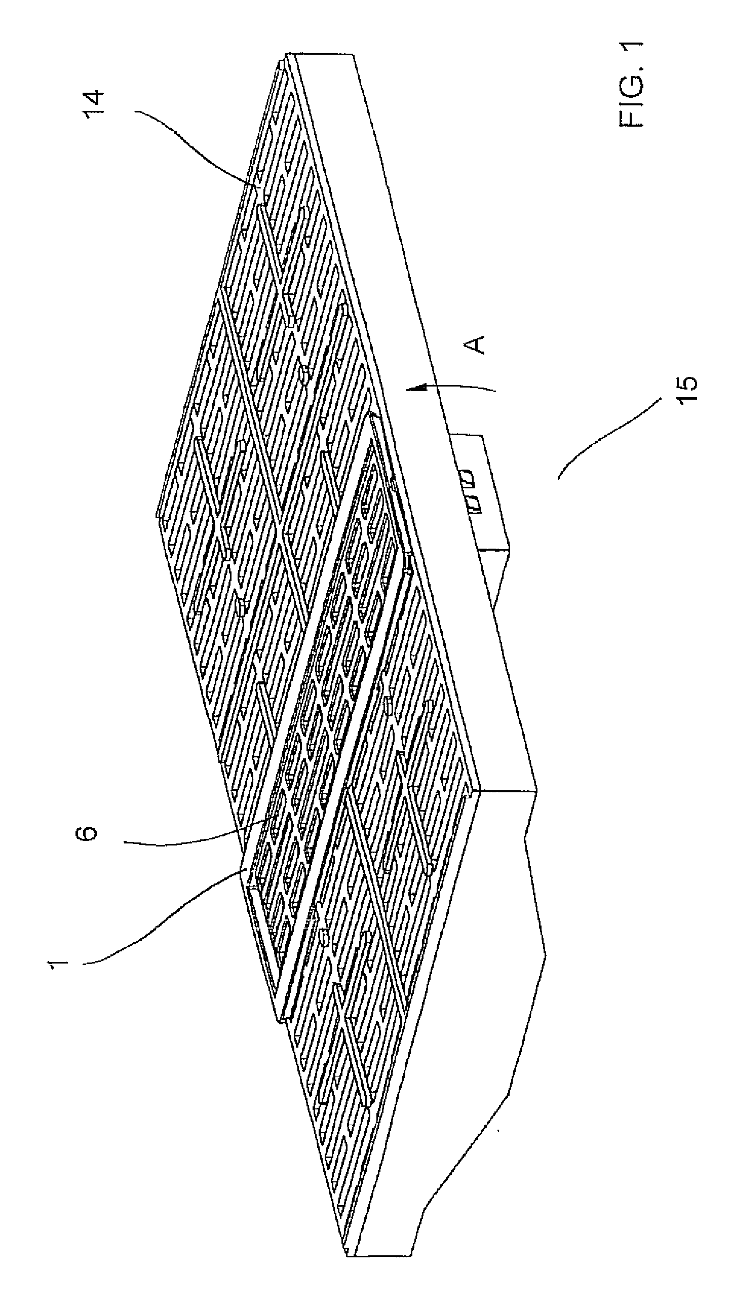
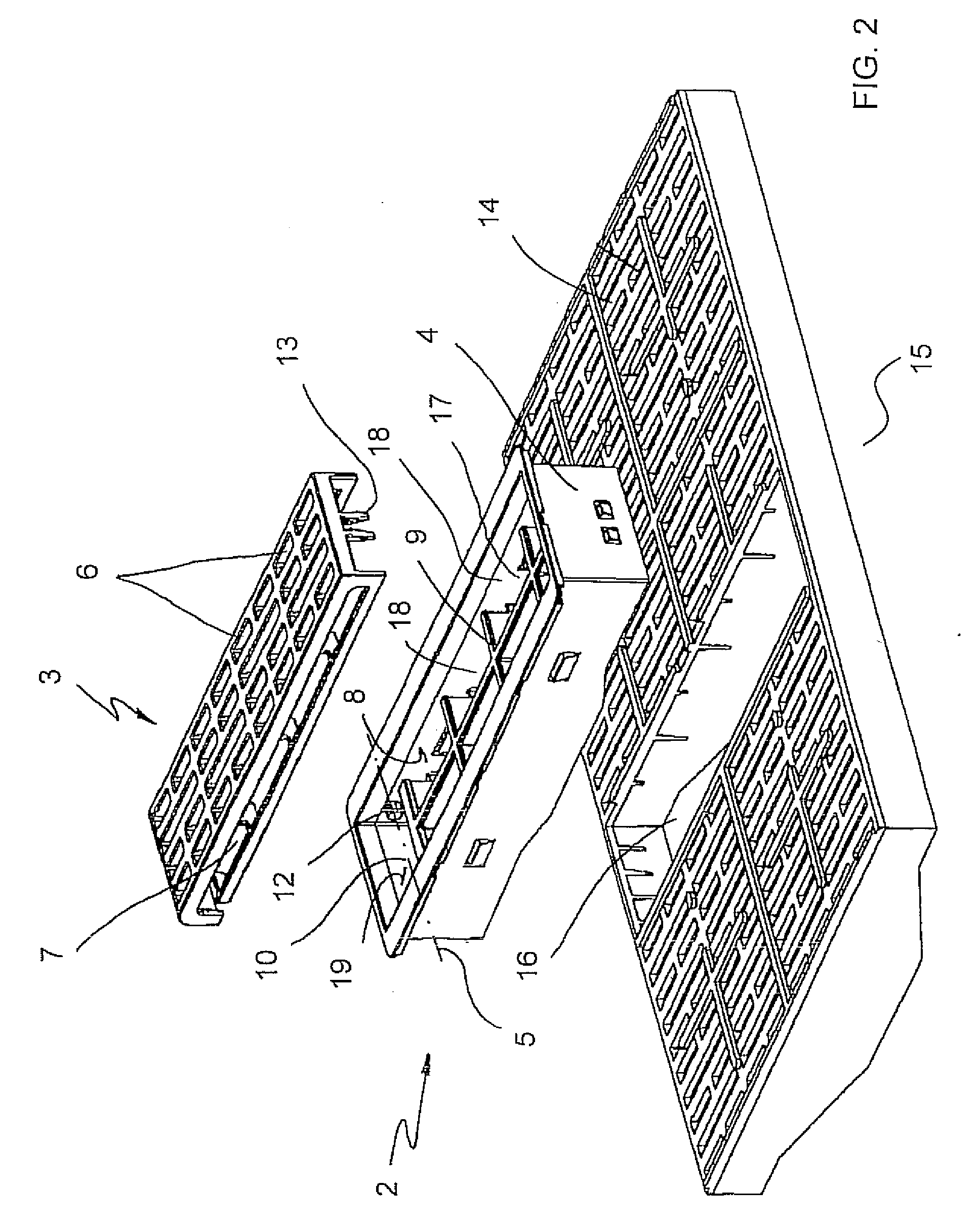
[0021]FIGS. 1 and 2 show a slatted device 1 according to the invention mounted in a suitable housing 16 of a stable floor 14. In this case, stable floor 14 also has a slat. However, device 1 according to the invention can also be mounted on construction floors, without departing from the object of the invention, in other words, simplifying the cleaning of the stable compartment floor. Therefore, slatted device 1 is assembled so that it separates the stable compartment from the pit 15, not shown but referenced, as being located below the floor 14.

[0022]As it can be better seen in FIG. 2, the slatted device mainly comprises a chassis 2 and a movable trap door 3. Trap door 3 has a plurality of openings 6 intended to prevent the excessive accumulation of excrements. Chassis 2 comprises a removal hole 17 over which trap door 3 is assembled. Between chassis 2 and trap door 3, sliding hinge means 11 are provided that allow trap door 3 to swing and move with respect to chassis 2, so that sa...


PUM


Abstract

Slatted device for stable floors. The device is suitable for being installed as a separation between a waste pit and stable compartment of stabled animals. The device comprises a chassis and a movable trap door having a plurality of openings. The trap door rests on the chassis. A sliding hinge means is provided between the chassis and trap door and the trap door can be moved to a position in which the trap door extends below the chassis.

Description

FIELD OF THE INVENTION [0001]The invention relates to a slatted device for stable floors, suitable for being installed as a separation between the waste pit and the stable compartments, comprising a chassis and a movable trap door with a plurality of openings, with the trap door resting on the chassis.STATE OF THE ART [0002]The floors of the compartments of stabled animals usually have grooves or openings that separate the animals' compartments from the pit below for collecting their excrements. The grooves are sized so that in preventing damage to the animal's feet, they allow said excrements to fall into the pit. However, in the case of compartments for large animals, and particularly the compartments for mother animals, the volume of excrements and the small size of the grooves, does not allow the excrements to fall easily into the pit. This means that these compartments have to be cleaned manually by a worker.[0003]To facilitate cleaning these compartments, state of the art manh...

Claims


Application Information

Patent Timeline
IPC IPC(8): A01K1/01E04B5/00
CPCA01K1/0151
Inventor GUARDIA, GENER ROMEU
Owner ROTECNA
Why Eureka
Try Eureka