
Methods and systems for estimating compressor fouling impact to combined cycle power plants

a technology for power plants and compressors, applied in the field of methods and systems for estimating compressor fouling impact in power plants, can solve problems such as compressor fouling, severe performance deterioration, and loss of turbine capacity and efficiency

Inactive Publication Date: 2008-01-31
GENERAL ELECTRIC CO
View PDF13 Cites 21 Cited by
  • Summary
  • Abstract
  • Description
  • Claims
  • Application Information

AI Technical Summary

Benefits of technology

[0017]FIG. 3 is a block diagram of a control unit used in a method and system for determining compressor fouling impact, according to an illustrative embodiment of the presen

Problems solved by technology

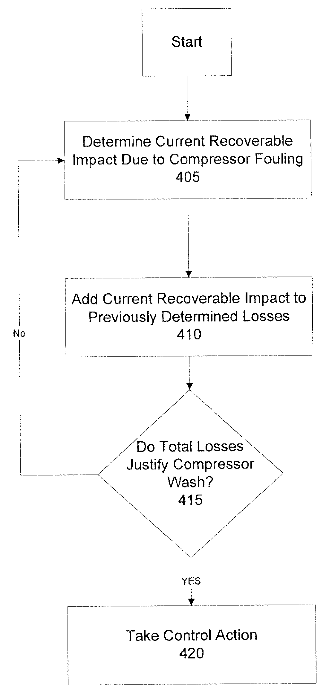
During the operation of a gas turbine, turbine capacity and efficiency losses may result from compressor fouling.
Compressor fouling may be caused by the buildup of airborne salt, dirt, or other particles on the blades of the gas turbine.
Such foulant deposits on the turbine blades may result in severe performance deterioration.
The effect of compressor fouling may be a drop in the airflow, pressure ratio, and compressor efficiency of the gas turbine, resulting in a drop in power output and thermal efficiency.
Performance deterioration may further lead to increased fuel consumption and higher operating costs.
While the gas turbine is offline, the power facility is losing potential revenue and profitability that could be achieved by selling the power generated by the gas turbine.
These preset schedules, however, typically do not take into account the different operating conditions which may exist for different gas turbines.
These prior art systems, however, do not consider the complexity of a combined cycle power plant.
Furthermore, the complexity of determining compressor fouling impact in a combined cycle power plant may be compounded by the presence of more than one gas turbine in the combined cycle power plant.
The prior art systems and methods of determining the most optimum time to perform an offline compressor wash are not appropriate for use in a combined cycle power plant.

Method used


Image

  • Methods and systems for estimating compressor fouling impact to combined cycle power plants
  • Methods and systems for estimating compressor fouling impact to combined cycle power plants
  • Methods and systems for estimating compressor fouling impact to combined cycle power plants

Examples


Embodiment Construction

[0019]The present inventions now will be described more fully hereinafter with reference to the accompanying drawings, in which some, but not all embodiments of the inventions are shown. Indeed, these inventions may be embodied in many different forms and should not be construed as limited to the embodiments set forth herein; rather, these embodiments are provided so that this disclosure will satisfy applicable legal requirements. Like numbers refer to like elements throughout.

[0020]The present invention is described below with reference to block diagrams of systems, methods, apparatuses and computer program products according to an embodiment of the invention. It will be understood that each block of the block diagrams, and combinations of blocks in the block diagrams, respectively, can be implemented by computer program instructions. These computer program instructions may be loaded onto a general purpose computer, special purpose computer, or other programmable data processing ap...


PUM


Abstract

A system and method for estimating the impact of compressor fouling in a combined cycle power block. The current performance of the combined cycle power block is determined and normalized to one or more reference conditions. A baseline performance of a gas turbine of the combined cycle power block is also determined. A predicted performance of the combined cycle power block is then determined by substituting the baseline performance of the gas turbine for the current performance of the gas turbine. A recoverable impact to the combined cycle power block due to compressor fouling is then determined by subtracting the normalized current performance from the predicted performance and a recoverable impact to the fuel consumption of the combined cycle power block is determined from the recoverable impact.

Description

FIELD OF THE INVENTION[0001]The present invention relates generally to methods and systems for estimating compressor fouling impact in a power plant.BACKGROUND OF THE INVENTION[0002]During the operation of a gas turbine, turbine capacity and efficiency losses may result from compressor fouling. Compressor fouling may be caused by the buildup of airborne salt, dirt, or other particles on the blades of the gas turbine. Such foulant deposits on the turbine blades may result in severe performance deterioration. The effect of compressor fouling may be a drop in the airflow, pressure ratio, and compressor efficiency of the gas turbine, resulting in a drop in power output and thermal efficiency. Performance deterioration may further lead to increased fuel consumption and higher operating costs.[0003]The gas turbine capacity and efficiency losses may be restored by an offline compressor wash in which the gas turbine is shut down and the turbine blades are cleaned. When performed correctly, ...

Claims


Application Information

Patent Timeline
IPC IPC(8): G06F19/00G05D1/00G06F17/40
CPCF04D27/02Y02E20/16F02C7/057F02C7/00F02C7/05
Inventor ZHANG, YANDAPECHTL, PETERPETEK, JOSEF
Owner GENERAL ELECTRIC CO
Learn More