
Thermal analysis system and method of drying the same

a technology of analysis system and temperature, applied in the field of thermal analysis system, can solve the problems of inability to acquire exact measurement values, inability to accurately measure, and condensation on the furnace body portion, and achieve the effects of eliminating labor, reducing noise, and reducing labor

Inactive Publication Date: 2008-01-31
HITACHI HIGH TECH SCI CORP
View PDF2 Cites 18 Cited by
  • Summary
  • Abstract
  • Description
  • Claims
  • Application Information

AI Technical Summary

Benefits of technology

[0011] In the invention, the inside of the purge box begins to be dried upon the activation of the thermal analysis system, and therefore the moisture including condensation and frost, which has adhered to the inside of the system before actuation of the cooling device, can be removed at the time before measurement without fail. That is, as the box inside is brought to a dried state before thermal analysis measurement of a specimen, the noise generation in the data in measurement owing to moisture is avoided, and thus a precise measurement can be performed.
[0035] The thermal analysis system of the invention can be made to control an operation of drying the inside of the purge box by performing a manipulation for ordering the end-of-work at the closing time. Therefore, it is possible to avoid the occurrence of condensation inside the purge box when the thermal analysis system is used next time.

Problems solved by technology

Particularly when a sample is loaded into and unloaded from the thermal analysis system, opening an opening-and-closing cover of the thermal analysis system causes the outside air to flow into the furnace body and the inside of the case, which can cause condensation on the furnace body portion and its surroundings, and further on a temperature sensor such as a thermocouple and others, leading to adhesion of water droplets and frost thereon.
This has been a cause of the impossibility of acquisition of exact measurement values.
In that situation, actuating the cooling device will cause generation of condensation and frost and the like in the thermal analysis system owing to the moisture remaining in the analysis system.
The thermal analysis system has the disadvantage that the moisture, particularly the moisture adhering to a cooling module and the like cannot be removed easily even by supplying dry gas or heating surroundings of a specimen thereafter.
This moisture causes the temperature to fluctuate and generates noises in measurement data.
However, there is the problem that in the case where the drying is performed through both drying by gas and heating of the heater block before actuation of the cooling device, excessively raising the drying temperature damages the cooling module (especially, a leading end of the cooling rod) inserted in and connected with the thermal analysis system when the cooling device is e.g. an electric cooling device.
Since the preferable drying time and the drying temperature vary depending on a cooling method including the type of a cooling device and its connection mode as stated above, their management has been a difficult and troublesome work.

Method used


Image

  • Thermal analysis system and method of drying the same
  • Thermal analysis system and method of drying the same
  • Thermal analysis system and method of drying the same

Examples


Embodiment Construction

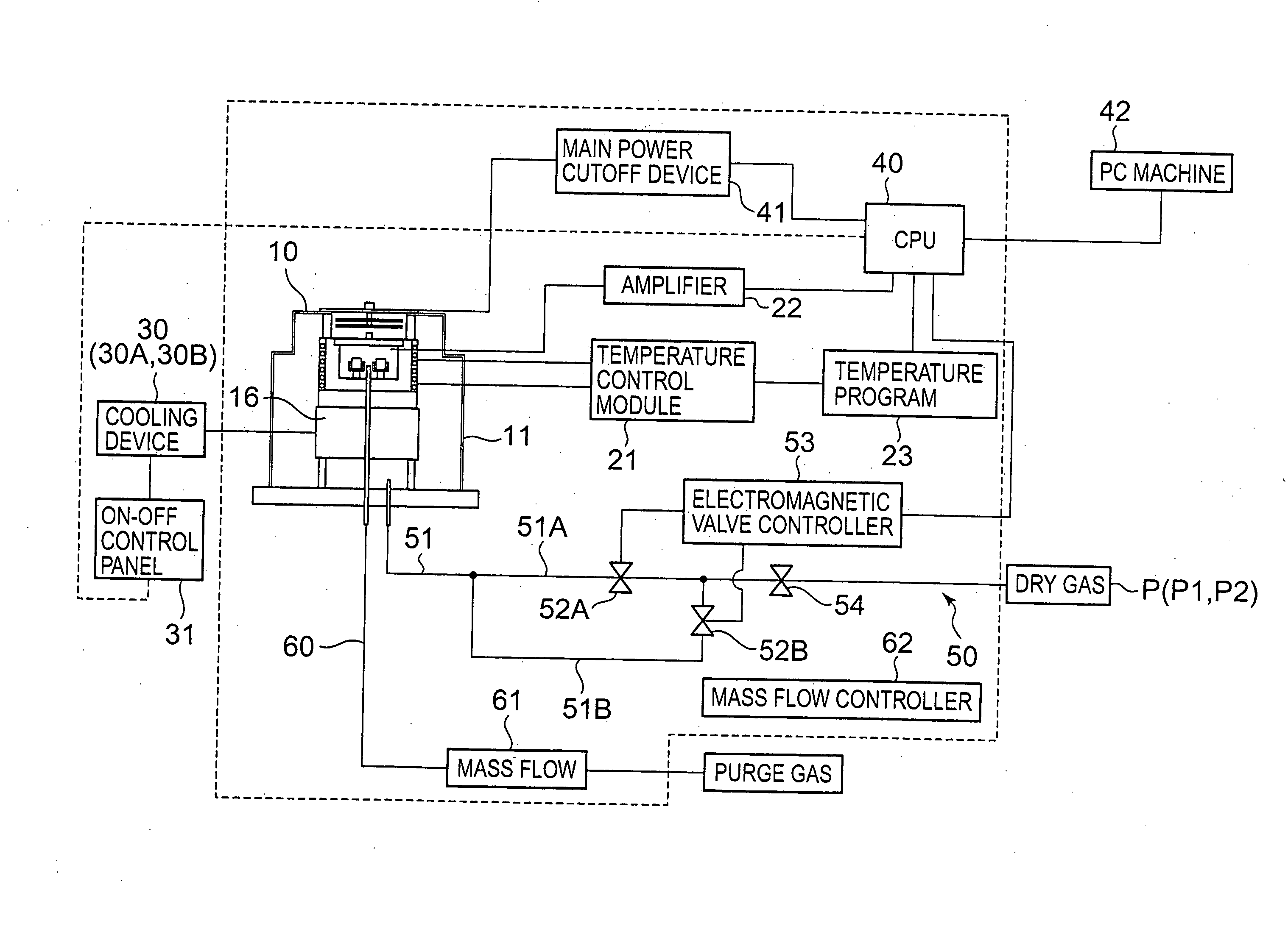
[0044] A thermal analysis system in accordance with an embodiment of the invention and its drying method will be described below with reference to FIGS. 1 to 8.

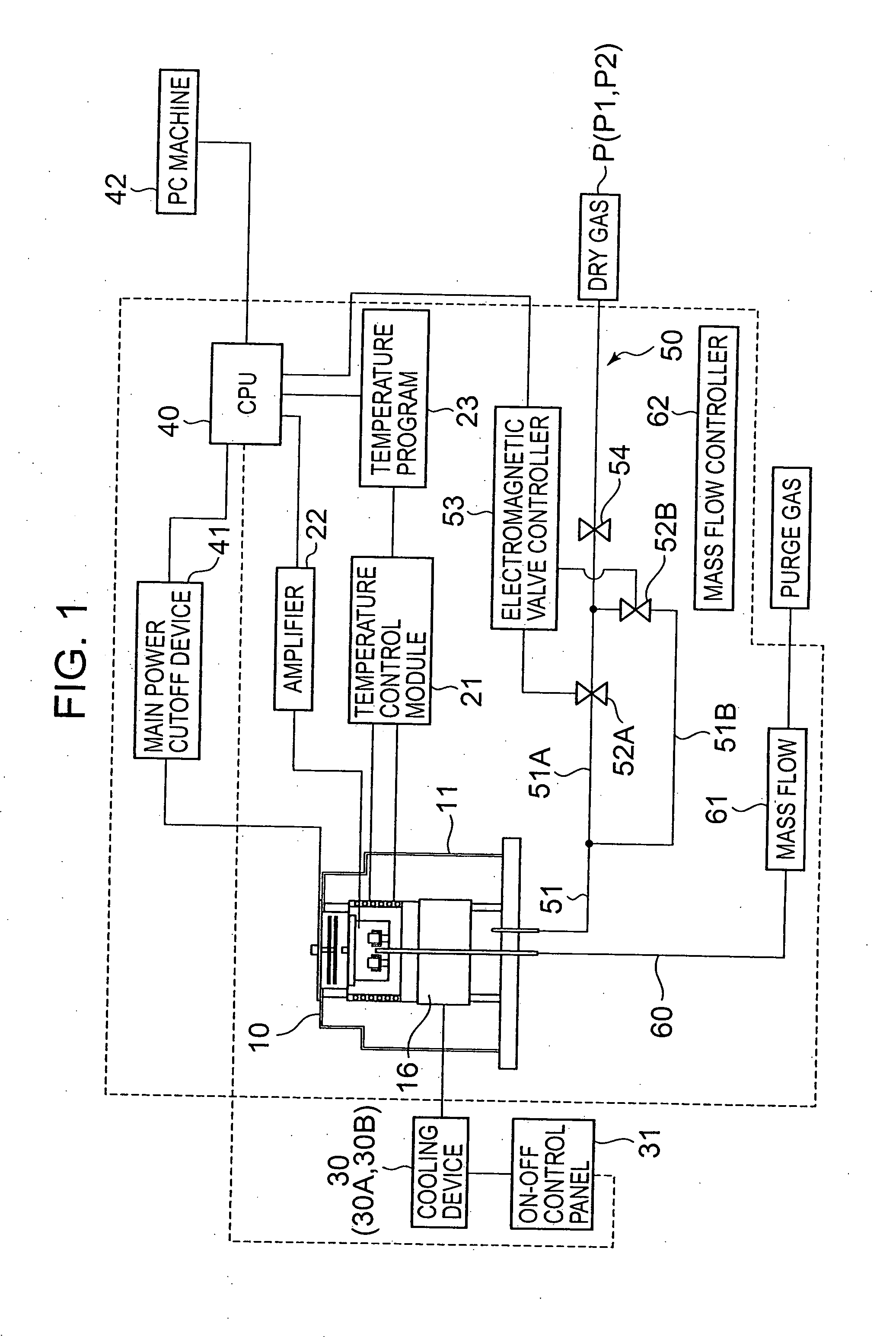
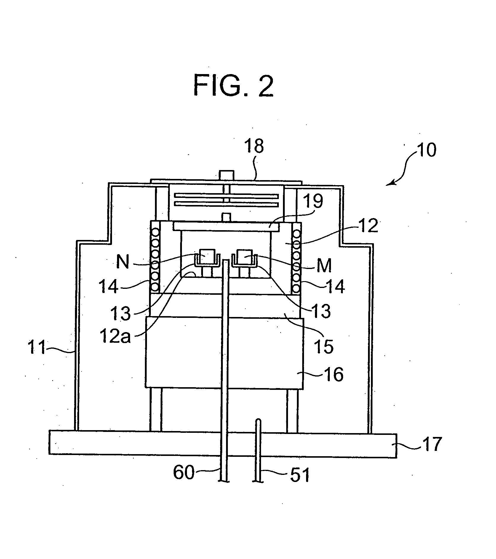
[0045]FIG. 1 is a block diagram for showing a general outline of a drying method of a thermal analysis system in accordance with an embodiment of the invention. FIG. 2 is the view showing a thermal analysis system. FIG. 3 is a flow chart of an opening time dry process when non-electric cooling is selected. FIG. 4 is a sequence diagram of the opening time dry process when non-electric cooling is selected. FIG. 5 is a flow chart of an opening time dry process when electric cooling is selected. FIG. 6 is a sequence diagram of the opening time dry process when electric cooling is selected. FIG. 7 is a flow chart of a finishing time dry process. FIG. 8 is a sequence diagram of the finishing time dry process.

[0046] As shown in FIG. 1, the method of drying a thermal analysis system in accordance with the embodiment is adopted for ...


PUM

PropertyMeasurementUnit
temperatureaaaaaaaaaa

Abstract

To enable the reduction in working efforts by hand by performing control a drying operation by appropriately selecting dry conditions depending on the connection mode of the cooling device, and removal of moisture and the like without fail. The thermal analysis system uses a heater and a cooling device to raise and decrease the temperature inside the purge box. In the drying method for the thermal analysis system, the drying operation is performed by: previously setting dry conditions depending on the connection mode of the cooling device; starting control of an opening time dry process upon activation of the thermal analysis system; supplying a predetermined amount of dry gas into the purge box in accordance with the dry conditions corresponding to the selected connection mode of the cooling device with the cooling device kept off; and making the temperature control module control the temperature of the dry gas.

Description

[0001] This application claims priority under 35 U.S.C. §119 to Japanese Patent Application No. JP2006-203849 filed Jul. 26, 2006, the entire content of which is hereby incorporated by reference. BACKGROUND OF THE INVENTION [0002] The present invention relates to a thermal analysis system such as a differential scanning calorimeter and a method of drying the same. [0003] Conventionally, with a thermal analysis system, such as a differential scanning calorimeter, having a furnace body therein, an analysis has been performed by: loading a sample (a specimen) in the furnace body; using a heating device and a cooling device to raise and decrease the temperature of the sample to change the sample in temperature; and measuring absorption and radiation of heat by the sample in the form of an amount of heat. During such measurements, the temperature of the furnace body is lowered to e.g. a temperature of −70 to −150° C. constantly or temporarily. That is to say, the furnace body portion and...

Claims


Application Information

Patent Timeline
Patent Type & Authority Applications(United States)
IPC IPC(8): G01N25/20F26B3/04
CPCG01N25/20
Inventor NAKATANI, RINTAROKINOSHITA, RYOICHINISHIMURA, SHINYA
Owner HITACHI HIGH TECH SCI CORP
Learn More